< Driving Wheel Cutting 1 >
The driving wheel diameter is 208 mm, which
is beyond the swing over bed of Myford Super
7. So the wheels must be turned in 'gap'
between the headstock and the bed. It causes
many restrictions. Also, phase difference
of the wheels is 120 degrees instead of 90
degrees. Moreover, axle diameter of the second
driving wheels is larger than that of the
first and the third driving wheels. I spent
much time for investigating procedures of
cutting the driving wheels.
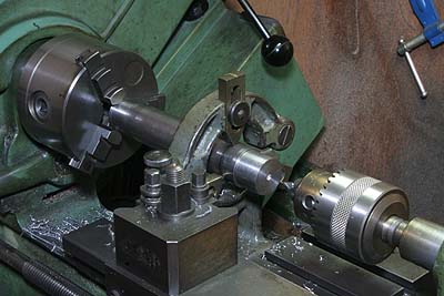
I prepared the axles first. The procedure
is the same as bogie truck axle. At the present
stage, the second axle is still finished
straight.
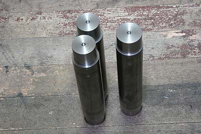
Full size driving axle has the thickest sections
in its both ends where the wheels are pressed
in. In case of model locomotive, the press
fitting sections are normally turned down
from a rod blank. As a result, the middle
section of the axle is far thicker than the
scale size. My loco's axles became 30 mm
diameter.
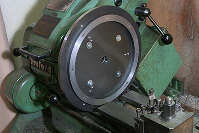
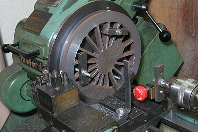
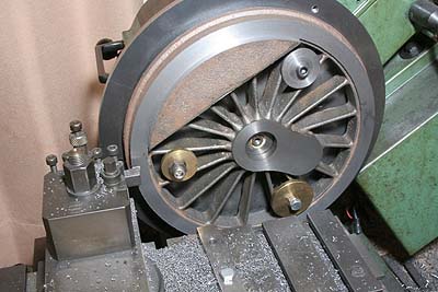
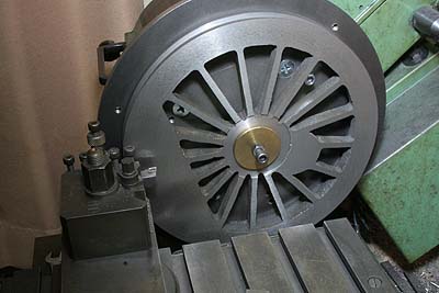
The photo shows extended face plate for turning
driving wheels. Laser-cut large disk is bolted
down onto the standard face plate. The ring
is also laser-cut and bolted onto the disk.
And then, face of the ring is trued up by
a clean cutting. The ring will hold the wheel's
rim or back side face truly square.
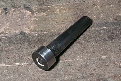
I prepared wheel centering spigot. Steel
round bar was silver soldered onto a MT2
blank arbor. And then the round bar is turned
down to the second driving axle's diameter
(thicker). Because of narrow 'gap', the spigot
has to be removed in every time I exchange
wheel castings. Every time I drive the spigot
into the headstock, the center is kept truly.
Incidentally the spigot has screw holes at
both ends, so as to secure wheels by its
center.
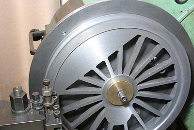
I started with the second driving wheels.
First the reference plane is cut in the back
side of the rim. When clamping, three small
thin plates are sandwiched between the jig's
ring and the wheel at every clamping positions,
so as to avoid distortion of the casting.
Because of huge diameter, I could not increase
turning speed more than 50 rpm. So it took
much time for one cut. I employed a limit
switch to stop the machine at desired position.
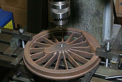
Centering is done with dividers. I cleaned
the boss center, scribed four arcs like '#'
from rim's inner edge in four directions,
found center from the mark '#' and drilled
the center hole with a center drill.
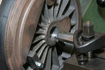
A hard center in the tailstock pushes the
wheel casting at its center against the jig,
and then the wheel is clamped between its
spokes. After that the center hole for axle
is drilled and extended by a boring tool,
using actual axle as a gauge. When I started
turning with 250 rpm, terrible quake happened
because of the casting's big counter weight.
I had to reduce the speed to 160 rpm.
Before release, the boss surface is cut and
finished. I cannot help cutting a part of
counter weight, because outer end of the
boss interferes with inner edge of the counter
weight.
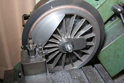
The rim is finished together with outer face
of the counter weight. Note the casting is
centered with the spigot.
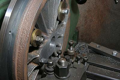
So as to finish the counter weight surface
without disturbing the boss, the casting
is clamped eccentrically on the jig by screw
stud and nuts
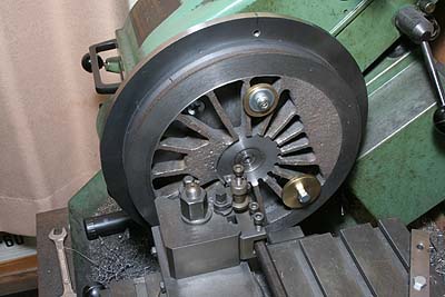
The casting is centered again with the spigot.
Groove between the rim and the counter weight
is cut by a parting tool. The parting tool
is deformed to suit face cutting. That is
to say, outer edge of the tool is ground
diagonally.
Back face of the boss is cut by boring tool.
After that, the center hole should be chamfered
in order to clear small fillet at the axle's
shoulder. Incidentally, I designed the boss
backside height lower than the rim backside
height, in other words, the axlebox will
go into the wheel, so as to secure much side
play of the driving wheels.
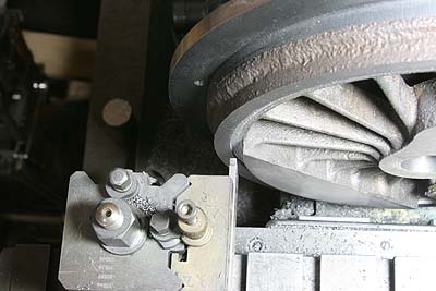
When finishing outer back surface, the casting
is clamped at its center. The spigot is pulled
from the head stock end, in order to avoid
the slack by the top screw. Note the screw
head between the spokes to prevent the job
from slipping.
Back side recess is cut by a knife tool.
Again the tool is deformed to suit for face
cutting.
That's all of this month. It takes really
much time to cut driving wheels...