< Cylinder Safety Valves >
It's been a long time no report! I resumed C53 construction from cylinder safety valves.
Cylinder safety valve is safety valve mounted on each cylinder head. It's a tiny version of typical safety valve. I plan to set the boiler working pressure to 0.4 MPa, so I set the cylinder safety valve to 0.5-0.6 MPa. As C53 has three cylinders, I have to make six safety valves.
The drawing shows safety valve section. The valve ball is 1/8" dia. The actual safety valve has adjustable plug, but I adopt fixed plug. The body has four side slots to release steam.
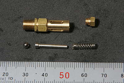
The photo shows all of safety valve parts. Brass body and plug, SUS303 stem, SUS304 coil spring and ball valve. The body's side slots are cut by end mill. The stem is silver soldered from two rods and cut bottom recess.
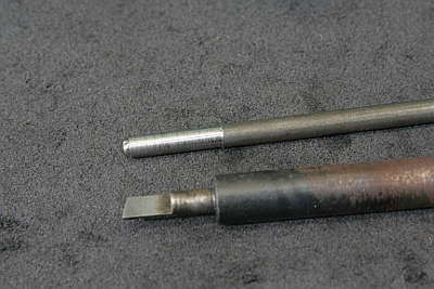
These are tools for valve seat cutting. The upper is a bar with a chrome ball for 'seating'. The lower is D-bit to cut the valve seat in 15 degrees.
Desired spring force is calculated as Pressure multiplied by Area. The area is cross section of the seat hole. On the other hand, intensity of coil spring is calculated as follows.
Intensity:W/F=d^4*G/(8*N*D^3)
F:Deflection [mm]
W:Load [N]
N:Number of active coils
D:Mean diameter [mm]
d:Wire diameter [mm]
G:Elastic modulus(stainless steel= 68500)
From the above conditions, optimum coil spring is designed as follows.
F=2.0 [mm]
W=0.28 [N]
N=7
D=2.8 [mm]
d=0.4 [mm]
Seat diameter=2.5 [mm]
Working pressure=0.58 [MPa]
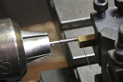
Direction of helix has no sense for function, but right-hand coil is standard in Japan. With the lathe reverse-turn and coiling from left to right, as a result, the coil becomes right-hand. Coil pitch is adjusted with lathe's power feed setting. When coiling non-active part of the coil, the power feed is released.
Due to 'springback', the coils inner diameter becomes 10 to 20 % larger than the mandrel diameter. At the same time, the number of coils decreases and coil pitch increases. It is better making test piece to check the springback.
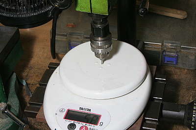
I measured spring intensity with a kitchen scale, chucking a shorter bar and holding a coil spring around the bar toward the scale stage. Measure pushing distance and pushing force. When the scale shows 100 g, the load is 0.98 N(Newton). Note the stage itself slightly moves downward due to the load.
I made a test piece and measured. As a result, coil intensity was lower than calculation. So I decrease the number of active coils from 7 to 6. The chart shows intensity of 6 coils. I intended to make uniform springs but varied like this.
Each coil shows smaller slope near the origin. I guess non-effective coils have small gaps and, at start, they become effective and weaken the spring.
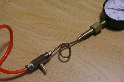
Each safety valve was tested with compressed air. Note there is a safety valve at middle of the hexagonal bar between the tube and the pressure gauge. At first each spring is made longer than the design, then pinched in order to get 0.5 to 0.6 MPa working pressure.
Working pressure was also lower than calculation. So I increase the deflection from 2 mm to 2.5 mm. The cause is unknown but possibly there is small leak under the ball and the effective area increases. Anyway it was good to do not only calculation but also measurement.
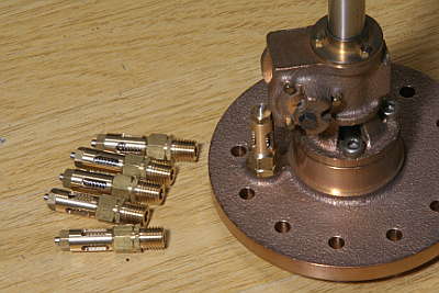
The safety valves are finally screwed into the cylinder heads. I employed Loctite 510 for sealing. The photo shows outer cylinder's front cover.