< Cylinder Head Covers 2 >
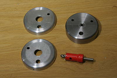
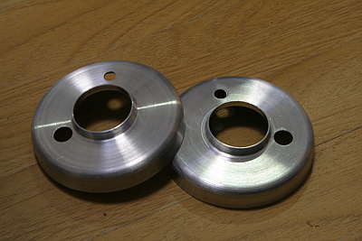
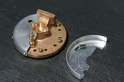
All of the head covers have holes for safety valves and others. It is difficult to drill thin aluminum plate cleanly. So I modified the spinning die as a drilling jig. The right-hand item in the photo is the jig and the left-hand are drilled covers.
The outer cylinder's front covers have center holes for the piston tail rod bushes. I have to form a forward flange around the hole. It is difficult to do it with spinning process, so I did it with press process. The drawings shows the press molds.
The head cover is put between two molds and a punch pushes out the forward
flange. Both molds have inner holes. The left mold (bottom side) has the
same diameter as the punch, while the right mold (top side) has the diameter
+ cover thickness x 2 + 0.2 mm. The punch has tapered top in order to press
out the flange slowly. In the right mold, the edge around the hole is rounded.
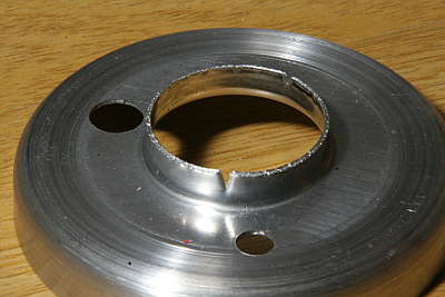
The center hole's start diameter is smaller than the final diameter. I adopt 16 mm start diameter for 28 mm final diameter and 5 mm flange height. The hole is cut with a hole cutter. (upper photo)
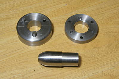
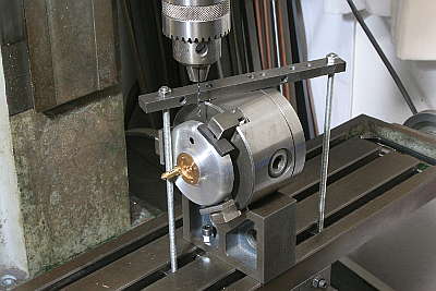
The two molds are modified from the spinning die and its base plate. They are fit together with two holes and pins. The punch has a step for collet chucking.
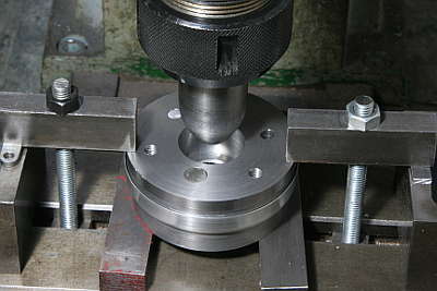
I utilized milling machine and set up as the photo shows. The cover with the molds are push hard against the stage, so as not to slip out during press. Grease is applied freely to the punch and the punch is slowly push into the molds.
The first trial was failed. Surface of the frange was broken. Next I increased the start hole diameter to 19 mm and also increase the play of the top side mold's hole diameter from 0.2 mm to 0.4 mm.
The second trial succeeded. I cleaned the edge of the flange with a file and all of surface is finished with emery cloth.
The covers are fixed on the cylinder heads with screws around the cover flanges. It will be done after bolting the cylinder head onto the cylinder block. So I have to choose the screws' position carefully.
The photo shows how to open screw hole around the flange. A pair of cover and cylinder head is fixed in three-jaw and rotated on a v-block. I drilled through the cover and countersunk the cylinder head. After that, I removed the cover and cut screw holes on the cylinder head. I utilized 2 mm screws.
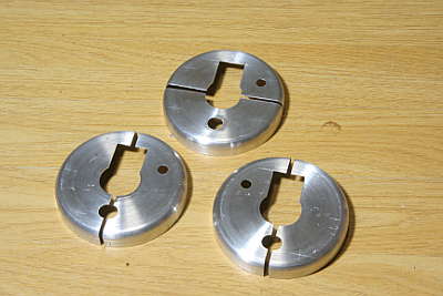
Due to the cylinder back head form, the back covers have keyhole type holes
and they have to be divided in two parts. The outer covers are divided
in left-right pair, while the inner cover is divided in top-bottom pair.
I divided them with a fret saw.
Some of divided covers have no space for screwdriver around the flange. In such case I cut screw holes on the top side of the covers. There is gap between the cover and the cylinder head. So I utilized brass pipes to support screws.
The photos show how to mount outer cylinder front cover. After fixing the cover, the piston tail rod bush is bolted on the cylinder head.
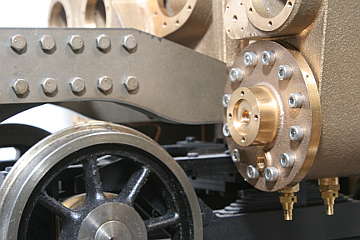
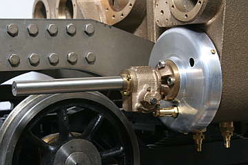
For the photographing, the covers are fixed onto the cylinder heads alone. I repeat that the covers actually have to be set after bolting the cylinder heads onto the cylinder block.
