< Inner Main Rod >
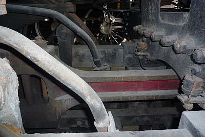
Although it is almost invisible, the inner main rod is symbolic part of
the prototype. The photo shows inner main rod of the full size C53 in Umekoji
railway museum. I intend to finish the part as clean as the outer main
rods.
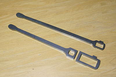
The rod body is made from laser cut mild steel parts. The lower two parts are for the inner main rod. The rod will be linked to the axle center, so it should be separated. A C-shape part holds separated bushes from back and is screwed onto the rod end.
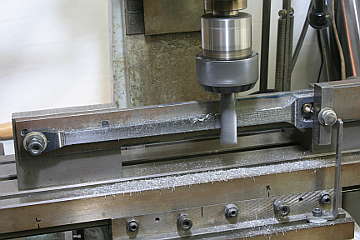
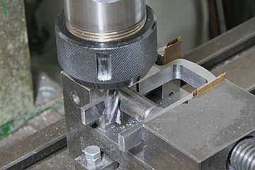
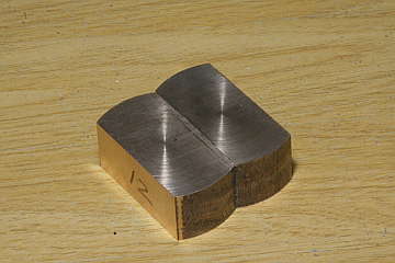
The rod body is cut the same as the outer main rod. The jig is modified from the outer main rod jig. Flute is cut in both sides. Three faces around the back end are cut precisely by end mill.
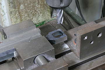
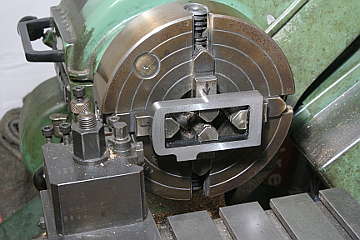
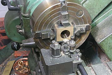
C-shape part is cut from the rectangle part. Its outer faces are ground and its side faces are cleaned in four-jaw.
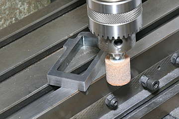
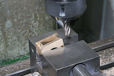
Inner faces are finished by end mill. Then, front beam is cut off and the rest is finished to correct C-shape. Note a support bar pushing C-shape against the vise jaws.
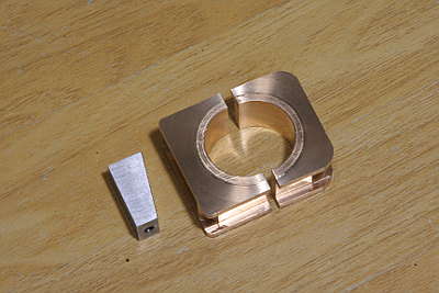
The separated bushes are made from gunmetal round bar. Each body is cut in four-jaw and glued together with instant glue. Then, remained two faces is cut and center hole is opened. After this, the two bodies will be separated or glued as required.
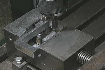
Grooves around the bushes are cut by end mill. The angle for wedge is set with the taper gauge reported last month.
The wedge is made from a steel bar. Here the taper gauge is utilized again.
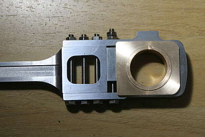
Assembled back end. The wedge is pulled from the bottom and the bolt is
secured by two nuts.
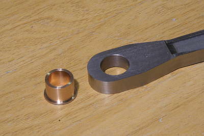
The front end of the rod is finished with a gunmetal round bush that will
be pressed-fit.
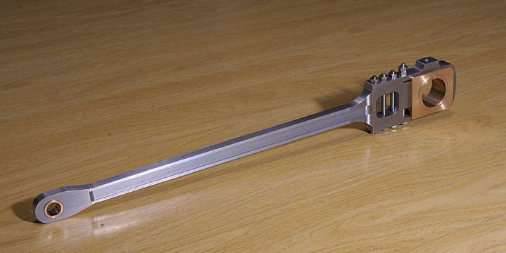
The inner main rod was completed. The screw hole at the back end top is for connecting lubrication tube. The hole is opened through the bush inside.
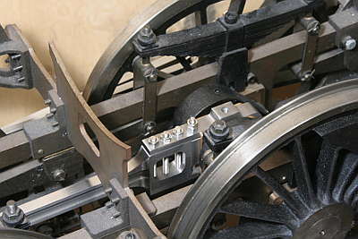
The rod was temporary incorporated into the eccentric axle and checked smoothness.