< Outer Crossheads 2 >
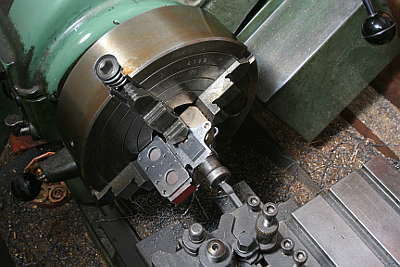
Crosshead and piston rod are joined with taper connection and secured by a flat cotter, same as actual C53 loco. First I opened taper hole on the crosshead. Scribe the center in the front face, align in four-jaw and drill prepared hole. Then bore taper hole by a boring tool in tilted top slider.
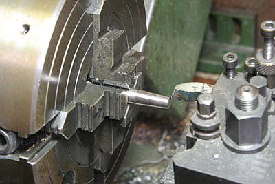
The piston rod must be cut at the same taper angle as the crosshead. Keep the top slider angle and turn the rod with a tool held in opposite side of the rod.
The drawings show section of the cotter. The yellow cotter has a tapered rear edge, so hammering the cotter causes pushing the magenta piston rod into the cyan crosshead.
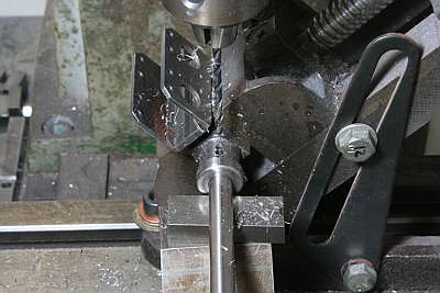
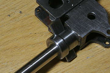
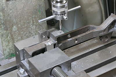
Slot for the cotter is cut as follows. Hammer the piston rod into the crosshead and drill through the crosshead with the piston rod at both front and back ends of the slot.
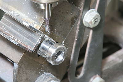
Tap out the rod and finish the slot with end mill. The bottom side is cut by turning the crosshead upside down.
Also finish the slot in the rod. Its read edge is finished tapered by tilting the rod in the vise.
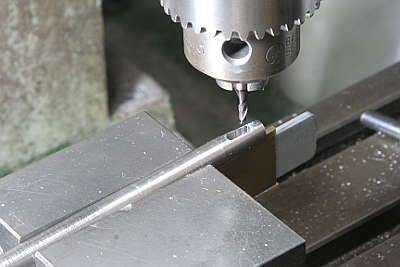
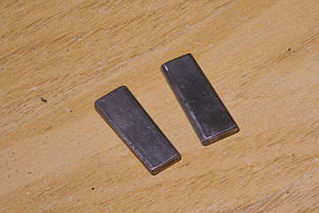
The cotter is made from 3 mm carbon steel plate. First, saw off the wedge shape and round front and back edges by 1.5 mm radius cutter. The cotter is currently longer than its final length.
Hammer the piston rod into the crosshead and hammer the cotter into them. After that, tap out the cotter and cut to final length and harden.
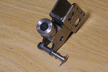
The crosshead has a pin for link. It is made of pin body, sleeve and stop ring. The stop ring is fixed with a split pin.
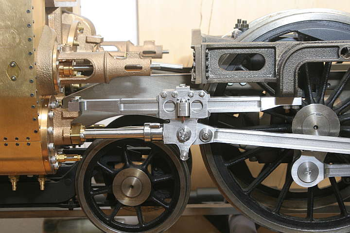
Mound the cylinder block on the chassis, fix the slide bar front end on the cylinder back cover, temporary assemble piston and crosshead without O-rings. Then I checked smoothness and found that the motion plate pushes down the slide bar's back end too much.
So I slightly cut out the bolting face of the motion plate, then drilled and tapped screw holes.
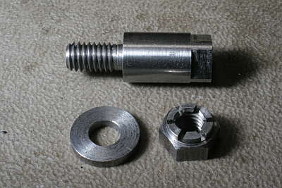
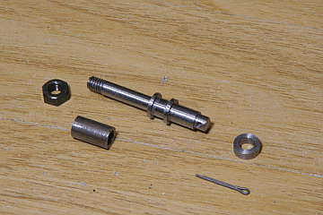
The gudgeon pin of the crosshead has 10 mm dia. body and 6 mm dia. threaded part. The crosshead hole is 6 mm dia. at top face and 10 mm dia. at bottom face. The pin is insert from bottom and fix the top with a nut. Note the pin's bottom end has 8 mm rectangle part for grip with a wrench.
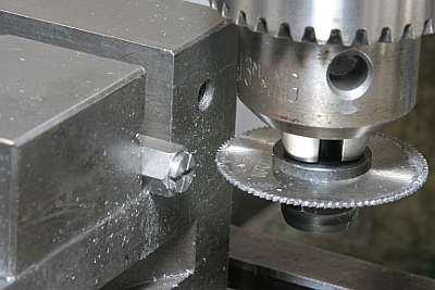
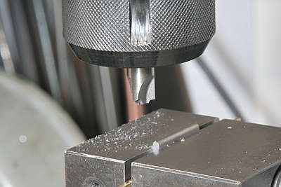
The nut is a castle nut made from 10 mm rectangle bar. The castle shape is cut as the photo shows.
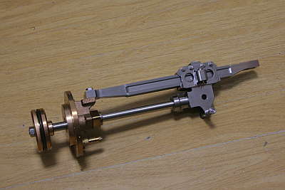
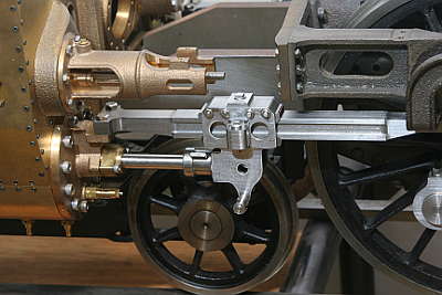
The piston, slide bar and crosshead is partly assembled. They can be mounted to the cylinder block together.
Mount them with O-rings and connect main rod. Roll on the track and check smoothness.