< Pilot Deck 2 >
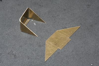
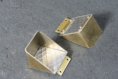
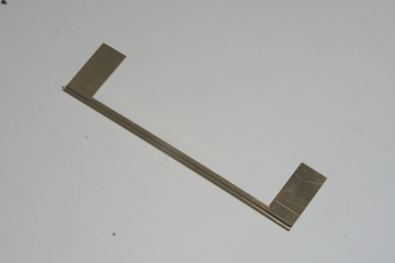
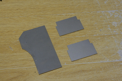
Start with fabricating the embedded steps for the valvegear covers. First, I fabricated the inner walls of the embedded section using a single piece of brass sheet for the left, right, and rear walls. The photo shows the cut brass sheet before and after forming. The protrusion at the bottom center is designed to secure the bottom plate. Below, I describe the forming process in detail.
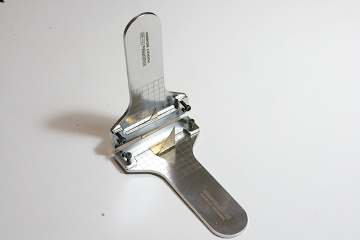
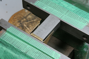
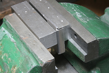
The left and right triangular sections were bent first using a bending jig, as shown in the photo. Though the jig has limited bending capacity, it is convenient for small parts. The central section was bent next. Since a jig could not be used for this section, I used a vise setup, as shown in the photo, to bend it.
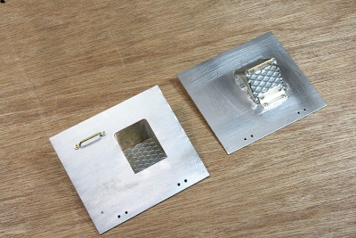
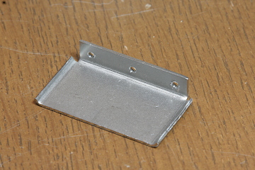
The bottom plate of the step is made of mesh patterned plate. The rear edge of the bottom plate was attached to the previously formed side plate, while the front edge was secured directly to the valvegear cover using an obtuse-angle brass plate.
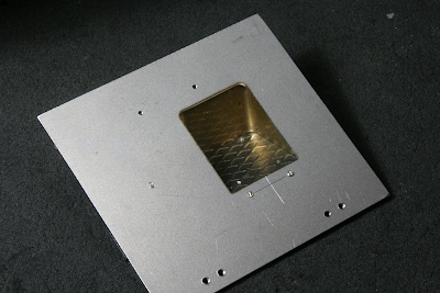
The step was temporarily fixed to the valvegear cover. It is secured with only two screws in front, screwed in from the bottom.
All joints were permanently fixed with soft solder, and the tips of the fixing screws were filed flush to remove any visible traces. Finally, the lost-wax cast handles, which I had prepared last month, were attached, completing the valvegear covers.
The prototype locomotive features an ash guard gutter installed below the smokebox door. Although it was a structural modification, it effectively deflects ash, so I decided to include it in the model as well. Additionally, it fills the gap between the smokebox and the side running boards. The gutter was fabricated from a 1mm brass sheet, as shown in the photo. The front edge was bent using a bending machine before cutting out the center section.
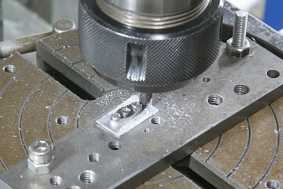
To mount the gutter, I chamfered the lower section of the smokebox front plate using a countersink cutter and drilled screw holes for securing the gutter.
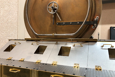
The pilot deck was temporarily attached to the chassis. The obtuse-angle plates at the rear end of the pilot deck were screwed to both the bottom of the smokebox and the running boards. On the actual locomotive, the gutter spans the entire width of the locomotive, but for aesthetic reasons, I limited it to the width of the smokebox in the model. I wanted to extend it slightly forward, but doing so would prevent the valvegear cover from opening.
Steps for climbing up to the pilot deck are attached to the lower sides. These were prepared using laser cutting. The photo shows the parts for one side.
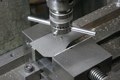
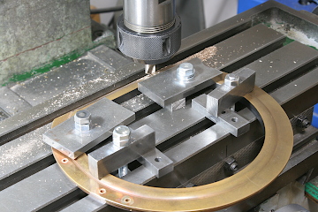
The post material was tapped. As always, all component mounting holes were drilled using coordinate control on the milling stage, with no manual transfer drilling.
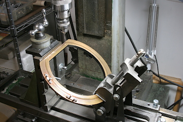
The step components were bent into shape. The curved sections on the sides were formed using a die made from steel flat bar with an inner radius cutter. Holes were drilled in the mounting section for attachment to the posts.
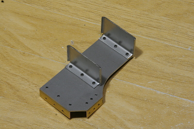
The steps were attached to the posts, completing the assembly. To secure them to the pilot deck, brass angle plates were added to the top and front.
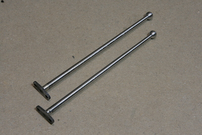
Poles are attached to the front left and right edges of the deck. These poles are tapered with spherical ends, making them difficult to machine. Below is the machining process.
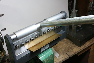
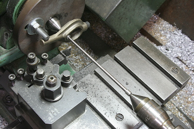
Since the total length of the pole is 110mm ,exceeding the travel range of the lathe's top slide, I could not use the conventional top-slide angle adjustment method for taper turning. Instead, I attempted tailstock set over method with both centers support, which I had not tried before.
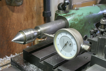
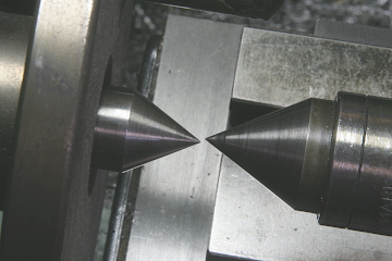
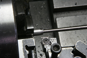
The Myford lathe’s tailstock has the set over function. I adjusted it to the required offset using a dial gauge. The right photo shows the set over center aligned with the spindle center. With the round bar supported at both centers, it rotates in a tilted position relative to the spindle, allowing a parallel cut along the bed to achieve the taper.
Due to material availability, I used free cutting stainless steel. I cut it slightly longer than needed and drilled center holes at both ends for center support. Because the material is long and slender, the cutting tool tended to deflect at the middle. To counter this, I made multiple sweeping passes with a sharp tool and performed final adjustments using file lathing.
The spherical end was machined in two halves, creating fine steps, and then finished with a file.
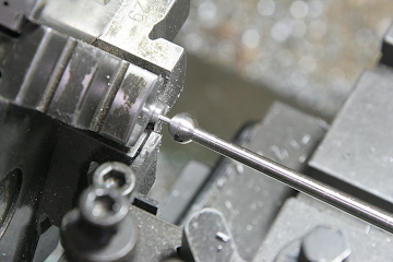
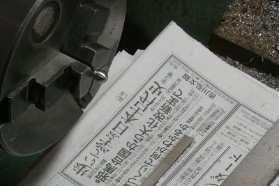
After cutting off both ends, I finished the base flat face and drilled a threaded hole. The spherical tip was refined using a file and sandpaper.
The base section for mounting the pole to the deck was machined using a rotary table. It was temporarily fixed to the pole body with countersunk screws and then silver-soldered for a strong bond.
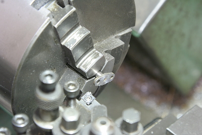
Finally, I ensured the base was perfectly perpendicular to the pole by re-machining the mounting surface on the lathe. To hold the tapered body evenly in a three-jaw chuck, I wrapped a thin brass sheet around the narrow section.
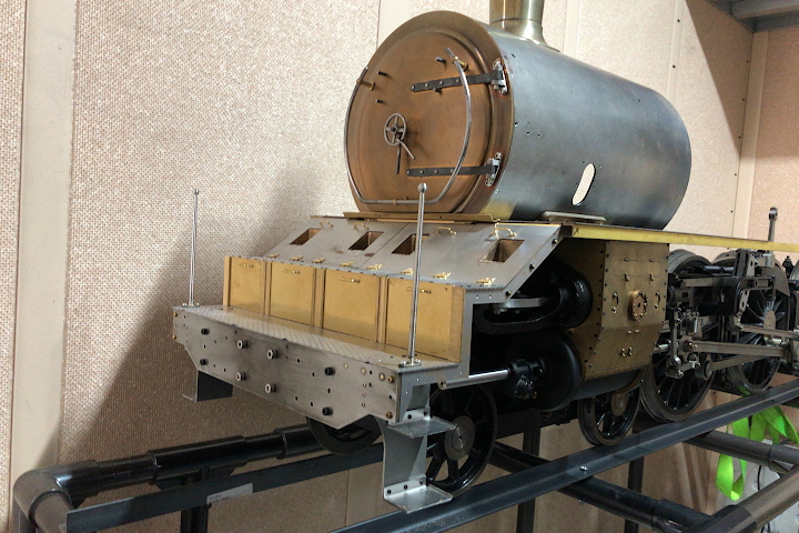
At this stage, all fabricated components were assembled onto the chassis. The model is now beginning to resemble a C53 locomotive.