< Cylinder Block 2 >
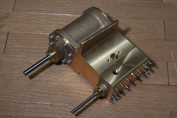
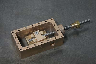
Slide valve stem is supported at both ends, those are the steam chest bush
and the inner motion plate bush. Therefore the steam chest bush is only
at the back side of the chest, and its length is enough short. As the steam
chest exists alongside the cylinder, the valve cannot land on the seat
by gravity. So I adopted comparatively low floating height, that is 0.5mm.
![]()
The valve body is made by brass cut out from 30mm rectangle bar by band
saw. Phosphor bronze is preferable as a material for the part, but I have
much stock of rectangle brass bar!
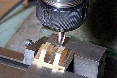
The blank is shaped into the slide valve by end mill. The center cavity
is to hold a valve drive block.
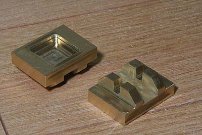
The photo shows finished slide valves. The recess for steam path at the
bottom should be cut precisely. Again, I cut roughly till the full depth
and finished only 2.5mm depth from the surface. The notches holding valve
stem determine the floating height of the valve with its depth.
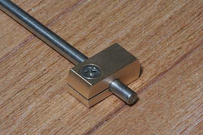
The valve drive block is made from a gunmetal round bar, cut to most rectangular
shape. Note a horizontal slit and a screw so as to secure itself on the
valve stem. The valve stem is a free-cutting stainless steel round bar.
The valve stem is sealed with an o-ring. The gland is cut from a hexagonal
brass bar. The valve has to fall freely when you lift up the drive block.
I adjusted the play between the valve and the drive block, also the play
between the valve stem and the slits.
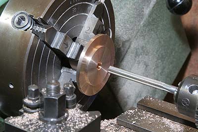
The cylinder covers are cut from prepared gunmetal castings. I started
from the back one. Outer diameter and the fitting step are finished. And
then the center hole is drilled and reamed.
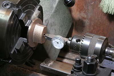
Reversed and centered with DTI, recess for o-ring and piston gland is finished.
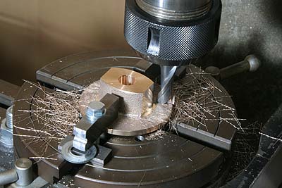
The bolting faces for slide bars are finished truly the same distance from the center. I employed rotary table to do that.
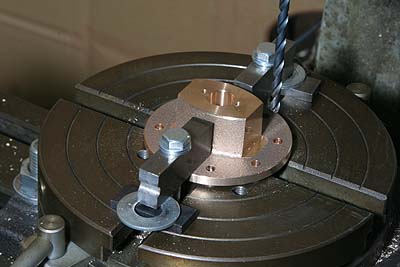
Utilizing the rotary table, outer circular-arranged holes are opened. Note
the screw holes for the gland are opened, too.
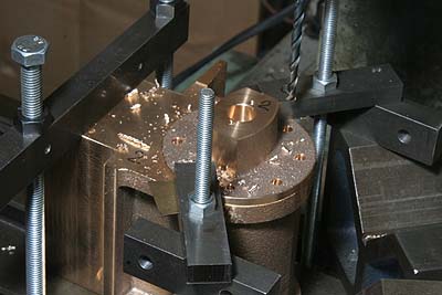
The front cover casting is prepared with a center spigot, so as to cut in the same manner as the back cover. The circle-arranged holes can be drilled through the back cover as a jig. Incidentally the right hand casting is a piston blank.
The circular-arranged holes on the cylinder block are opened as follows.
Set the cover upon the cylinder block and clamp them together, ensuring
the slide bar bolting faces is truly vertical to the valve seat face. After
that, countersink the cylinder block through the cover to form guide pits.
Remove the cover, drill the pits and tap threads.
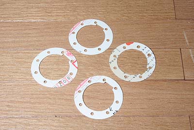
The cylinder gaskets are made from a post card. Printed full size drawings
by CAD, they are cut out by a paper knife.
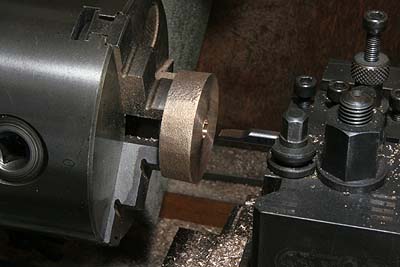
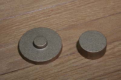
Same as the C53, I employed taper-fit between piston and piston rod. The
both ends of the piston blank are finished, and then the center hole is
cut taper with a boring tool. The taper should be 'opposite', namely the
deeper the hole is, the larger the diameter is. The reason of 'opposite'
is obvious if you compare the photo with the next one.
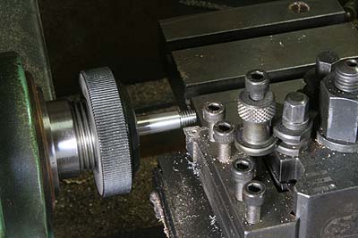
Holding the top slider angle, taper of the piston rod is turned. The thread on tip should be cut beforehand.
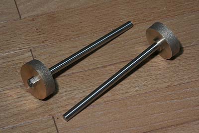
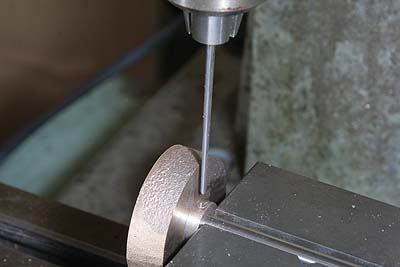
The piston is set on the rod with a nut. And then both parts are secured
with a taper pin. The second photo shows opening taper pin hole with a
taper pin reamer.
Finally, piston O.D. and o-ring groove are turned. The piston O.D. is finished
0.1mm under the bore I.D. The groove is finished as the o-ring will be
squeezed 0.2mm in its section diameter.
The whole cylinder parts are temporary assembled. The slide valve's sliding face and the opposite seat face are ground with a fine emery cloth laid upon a flat surface. The piston gland is turned from a brass rod. Here I am aware that the steam chest cannot pass through the main frame's rectangle hole due to the projection of the bush. So I will have to disassemble them later.