< Brake Gear >
The original design doesn't include brake
gear. Actually, active brake system is not
effective in case of such a light weight
locomotive. So I decided to make it as a
parking brake which requires less relative
components and is comparatively easy to make.
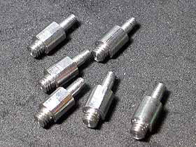
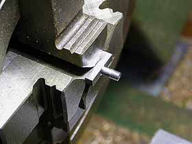
The picture shows hanger pins, which were
made from a round steel bar and will be screwed
into the main frames. The round side face
was slightly cut to a flat, so that the pins
can be fastened with a wrench.
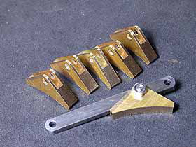
The brake blocks are made from a fat brass
sheet with a CAD paper pattern glued onto
it. After opening pinholes, cut off one by
one with a fret saw.
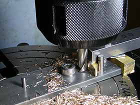
With a jig on the rotary table, outer 'V'
shape, the tread face and shoulders were
milled. Also the round tips of later items
(hangers, fork-ends, arms) were milled in
this stage.
Incidentally, my parts-making process is
random, even though I explained them sequentially
in the web site. Identical works of different
items are done in one stage.
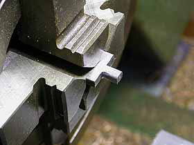
In the vertical slider, a deep slit was cut
with a metal saw. The same jig was employed
again.
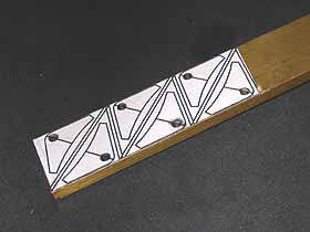
The picture shows drawings of the jig. The
black circles show 3mm and 4mm holes for
detachable pins. The leftmost pin corresponds
to the rotary table center. 4mm pins determine
angle of the job. Each red line shows cutting
line in each position.

The hangers were made from a flat steel bar.
The brake blocks were fixed on the hangers
with pins, nuts (for surface) and E-rings
(for behind).
The brake beams were also made from a flat
steel bar. The both ends were sawn out as
the photo, turned to a pin shape and partially
threaded in the four-jaw.
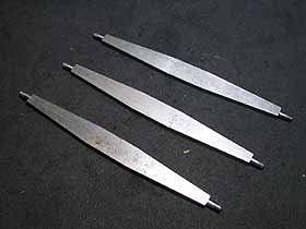
Three beams are glued one another, and milled
to a diamond-shape.
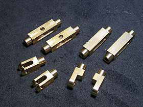
The forked ends were made from brass square
bar. Note some of them are integrated 2 in
1, as the brake rods will be aligned in a
line.
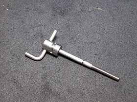
The brake handle was assembled from stainless
steel parts. The spindle was press-fitted
to the head and secured with a small pin.
The elbow was fixed in the head with Loctite.
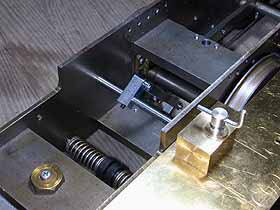
In the cab, there is no space for brake handle
column. So I mounted the handle directly
on the cab floor. The handle bush is just
a brass block on the running board.
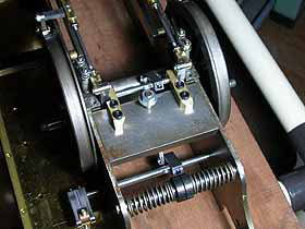
The handle is screwed into a phosphor bronze
nut which is sandwiched between two steel
arms. Due to operation of the handle, the
nut moves up and down and the pair of arms
move. Note the arm has oval hole to catch
boss of the nut (backside is the same). As
the arms will be completely hidden behind
the whistle, I didn't care for its look.
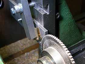
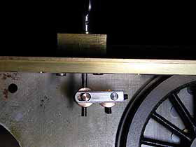
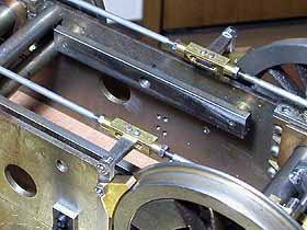
The photo shows a view from back of the chassis
upside down. When the arms (left bottom in
the photo) move, the first axle and the linked
second axle rotate, then the other arms at
each end of the second axle pull fork-ends
of brake rods, then the brake goes. The first
axle is hold in a pair of holes in the chassis,
while the second is supported with a pair
of brass brackets screwed onto a stretcher.
The brake rods were made of 3mm steel wire.
Each end was threaded and screwed into the
fork-end. End to end distance is adjusted
by the screws and secured with lock nuts.
Position of pins which secure the fork-ends
on the brake beams was checked from job,
so as to make all of brake blocks push the
wheels at a time.
The third beam is just under the ashpan.
So as to make the ashpan removable, the medium
part of the third beam was sawn out. Note
four rivets secure the fork-ends rigidly
on the beams.
Actually, we hardly have chance to use parking
brake in practice. It is rather for a model
enthusiast to claim, "She has real brake
system !"
| TOP | BACK | NEXT |