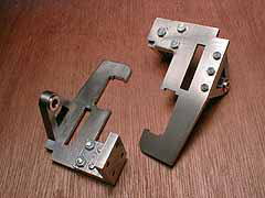
< Motion Plates etc.>
The motion plates for the William are plane
mild steel plates combined with brackets
which carry the expansion link. We can tackle
with them in the same way as the main frames.
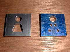
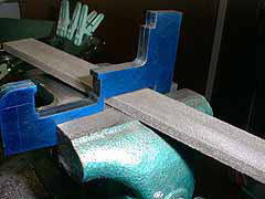
The brackets for the expansion link are made
of BMS flat bar. First the window was cut
out by drilling, sawing and filing.
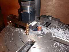
The triangle shape was end-milled on the
rotary table.
Both motion plates were temporary combined
with headless copper rivets and end-milled
together.
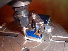
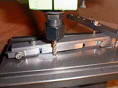
The grooves which hold the slide bars are
cut by a Woodruff cutter, using the slide
bar material as a gauge to get correct width.
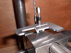
The motion plates have rectangle slots which
clear the radius rods. Start with drilling
in the both end, open the window with a fret
saw and finally file to desired shape.
The bracket is put on the correct position
of the plate, clamped and countersunk through
the hole in the plate. Then the bracket is
drilled and tapped.
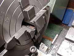
A mild steel angle is employed to fix the
motion plates onto the frames. The angle
is trued up in the four-jaws before using.
Bushes for the expansion links were turned
from a phosphoric bronze rod and press fitted
to the brackets.
I employed BMS flat bar with desired width
and depth for the slide bar. In this case
I don't have to do much more than cutting
the slant shape on the both end. I prepared
a jig which tilts the job in correct angle
during cutting.
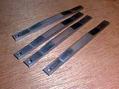
The excess areas in the both ends for clamping
will cut after the operation.
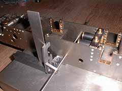
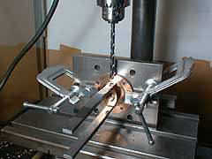
There are holes in the frames which indicate
the position of the expansion link. Holding
the link bracket of a motion plate with a
round bar inserted through the positioning
holes in the frames, the motion plate is
set vertical with a try-square and clamped
to the frames. Then drill through the frames
and bolted together. I added holes for 2mm
positioning pins.
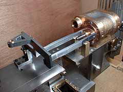
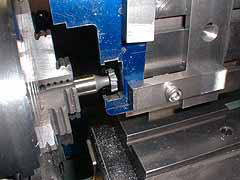
Lining the slide bar. Note a pair of brass
square posts which hold the slide bars in
correct height from the frame. Then the slide
bars are glued to the cylinder rear cover.
A counter sink is made in the bolting face
of the cylinder cover through the slide bar.
Then the cover is drilled and tapped.
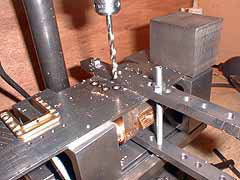
After positioning and clamping a cylinder
block, drill through the frame and make a
counter sink on the cylinder. I added holes
for positioning pins again.
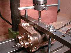
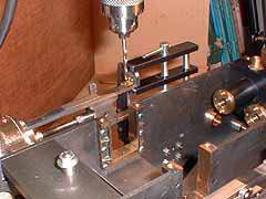
The cylinder block is drilled and tapped.
Note the nut on the tap as a stopper. Depth
of the hole should be decided carefully according
to the plan. If the bottom is too closed
to the main bore, the bore will be distorted
when tapping.
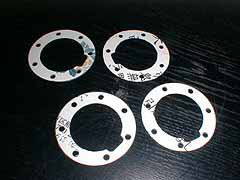
Position of the slide bar depends on the
thickness of the cylinder gasket. So we have
to prepare them here. They were made of 0.2mm
paper, printed by CAD and cut with a knife.
The rear end of the slide bar is fix to the
motion plate with a brass angle. The angle
is fix to the motion plate by iron rivets,
then bolted to the slide bar.
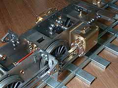
All of wheels and rods were mounted to the
frames and lubricated, then the chassis is
tested on a curved track. The weight of the
chassis is 13kg. With this adhesion, the
wheels should rotate smoothly without slipping.
Close your eyes and slowly push the loco
with a finger. If you feel a tightness then
open your eyes and check the position. Repeat
this operation and if the position is always
the same, the position is "hot spot"
to be eliminated.
It needed following adjustment to have satisfactory
result.
- The angles which hold the slide bar to the motion plate are slightly distorted with riveting, and push the slide bar toward inside. Then I corrected the shape with a flat file.
- The inner rear edge of the slide bar had sometimes touched the con-rod. Then I cut the edge slantwise.
- A connecting rod was slightly curved and prevented smoothness. So I carefully straighten them.
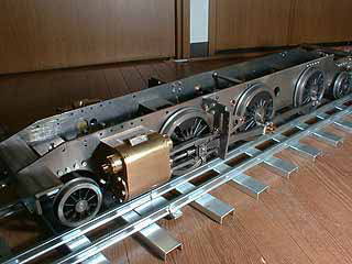
Rolling and rolling... Now is a time when
I look like a small boy to my wife !
| TOP | BACK | NEXT |