< Platework 2 >
[Brass angles and copper rivets for assembly]
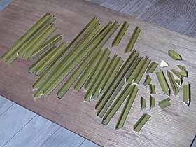
It needs a lot of brass angles to assemble
the side tank. At the corner of the tank,
Brass angles with 45-degree slant end are
employed. If three angles will be gathered,
two flats of an angle should be slant.
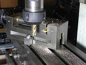
The photo shows how to finish 45-degree slant
end in two flats. In this case, the machine
vise is tilted 35.26-degree, instead of 45-degree.
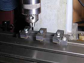
More than 200 copper rivets are necessary
for one side plate. I employed milling machine's
X-Y stage control. The photo shows preparation
of this operation. A length of steel bar
is bolted onto the stage. The bar should
be truly parallel to the stage. Then X-dial
collar is reset at the end of the bar, while
Y-dial is reset at the edge of the bar.
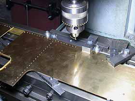
Center drill is used at start, and then straight
drill follows. A brass angle for assembly
has been glued behind the plate. Then the
drill goes through the plate and the angle.

If you assemble side tank with rivets, you
have to investigate the procedure carefully.
Otherwise, it will become impossible to continue
halfway. In my case, at the start, all of
angles on the side plate were riveted. After
that, front plate with angles was riveted
onto the side plate. I employed silicon caulking
to seal the angles, while the window bead
was soft soldered.
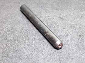
This tool is 'rivet snap' to form a snap
head at the tip of a rivet. However I utilized
it as 'dolly' which holds a rivet head and
guard it from distortion, when riveting.
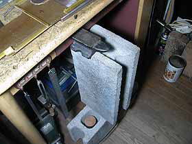
The rivet-snap was push into a hole on the
worktable, and supported by brick and anvil
from the floor. The side plate should be
parallel to the table, while riveting.
[Bending the roof]
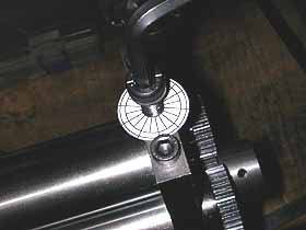
Now is the time for the bending roll work.
Actually, locomotive roof radius is too large
for this size of bending roll. The pushing
roll should be controlled in 0.05mm tolerance.
I controlled rotation angle of the pushing
bolt with a paper protractor glued around
the bolt.
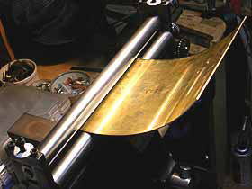
Careful operation is necessary. The pushing
roll should be truly parallel to the under
rolls.
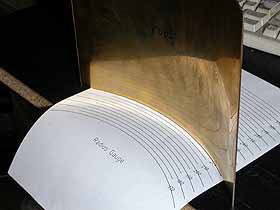
Paper radius gauge printed by CAD. Front
and back edges of the roof should be finished
in the same radius.
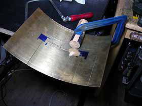
Area of 20mm from a side edge should be cut,
because the radius is not precise here. I
employed a round wood bar to fix the roof
on the table.
| TOP | BACK | NEXT |