 < Safety Valves & Water Unit >
The safety valve shown in the picture is
not from William's drawings. It comes from
'Mild Pop Safety Valve' presented by Gordon
Smith in "Engineering in Miniature"
in 2001. It has high venting capacity, low
hysteresis and mild action. Stuart Hardy,
a model engineer in N.S.M.E.E, introduced
the valve to me. He has already completed
the William with this type of safety valves.
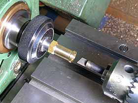
The valve body is made from hexagonal brass
bar. First, the bottom part was turned and
threaded. Then it was screwed into a mandrel,
turned, drilled and finished with a D-bit.
Note the mandrel was chucked in a collet
instead of three jaws. It means the mandrel
can reproduce true center in any future use.
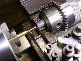
The valve stem is also made from brass. Note
a round bar with a center hole hold in the
tail stock, which supported the long and
thin material when turning.
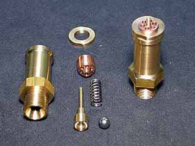
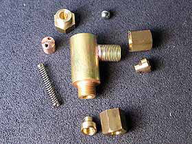
The safety valves exploded (left hand) and
assembled (right hand). The spring was coiled
by myself. The top ring is a lock nut which
secures the adjusting screw made from phosphor
bronze bar.
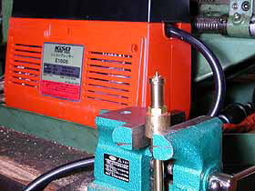
Venting pressure was adjusted with air-compressor.
The top screw was adjusted until the pressure
gauge of the compressor indicates constant
0.6 MPa. Final adjustment should be done
in the first steaming up, because venting
pressure of steam is different from that
of air.
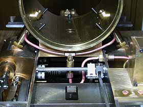
I designed the water unit at the rear part
of the loco, due to following demands.
- Abolish coal banker and rear water tank
in order to ease driver's operation.
- Mount 2 KG dead weight at the rear end
of the frames to improve axle weight balance.
- The hand pump should be mounted as rigidly
as possible.
- Driver can confirm side tank waterline
at a glance.
- Driver can confirm water flow from the
axle driven pump at a glance.
- Make available supplying water from a container
in the trolley.
- Test running without the side tank can
be done.
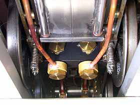
And the result is shown in the photo.
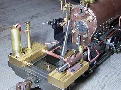
 As a dead weight, two brass blocks were mounted
on the rear buffer beam. The blocks have
inside water manhole and each block will
be connected to each side tank. The hand
pump is fixed rigidly onto the right hand
block and sucks water from the block. The
two blocks themselves were connected each
other with a balance pipe. The pipe has two
blanch to the pair of axle driven pumps.
The left hand block has a nipple at the rear
corner, which will be connected to a water
reservoir in the trolley. At the rear end
of the left hand block, there is a fat brass
pipe which works for three purpose as follows.
As a dead weight, two brass blocks were mounted
on the rear buffer beam. The blocks have
inside water manhole and each block will
be connected to each side tank. The hand
pump is fixed rigidly onto the right hand
block and sucks water from the block. The
two blocks themselves were connected each
other with a balance pipe. The pipe has two
blanch to the pair of axle driven pumps.
The left hand block has a nipple at the rear
corner, which will be connected to a water
reservoir in the trolley. At the rear end
of the left hand block, there is a fat brass
pipe which works for three purpose as follows.
1) Side tank water line indicator
2) Air venting hole of the water unit
3) Return flow catcher from the axle driven
pump
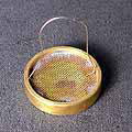
As a filter, a brass ring with fine brass
gauge is sunk into the tube (see small photo).
The blocks and connections will be hidden
between the floor and the running board.
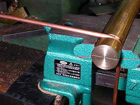
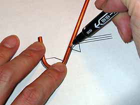
Free hand tube bending takes much time and
resulted in bad looking. I designed all of
tube bending in CAD and bent them before
silver soldering. The photo shows how to
bend a tube in required radius and angle.
For more precise bending, I employed full
size drawings printed out from CAD. I don't
like annealing because it makes copper tube
too soft to bear rough handling in practice.
The lowest part of the loco except wheels
is the suction fitting of the axle driven
pumps. I changed the design of them in order
to keep reasonable height from the truck.
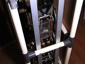
Some fitting works were done with the loco
backside up in the carrying case. If smokebox
can support the boiler weight, same trick
can be done for completed loco and it will
make maintenance much easier.
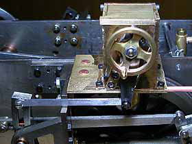
The lubricator is driven by one of expansion
links. This is standard of Japanese locomotive.
The photo shows all of the oil check valve
components. Ball valve is push against valve
seat with a coil spring via a cup. Note a
pair of holes in the cup for oil path.
Branch tubes from the oil check valve were
connected to both steam pipes from the smokebox.
The two tubes should be the same length and
height, otherwise the oil always drops into
one side cylinder.
All of the components for driving loco were
completed. In the next time, I will report
the first test running !
| TOP | BACK | NEXT |