< Superheater >
The William original drawings suggest a horizontally
divided smokebox for easy piping work. But
a divided tube losts its roundness and also
it doesn't look neat. So I left the idea
and instead designed smokebox, superheater,
steam pipes and cylinders as simple as possible.

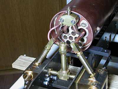
See the pictures. The tubes have no bend
except for the superheater inlet tubes. The
steam pipes are straight forward to the cylinders.
Procedure for assembly is as follows. First,
the steam pipes are inserted from inside
of the smokebox, and screwed deeply into
the cylinders, next the superheater assembly
is mounted onto the boiler tubeplate, then
the steam pipes are screwed back into the
elbows and fixed with locknuts in each end.
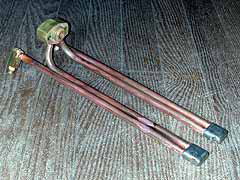
The superheater assembly is consist of a
brass wet-header, copper tubes, stainless
steel return bends and brass elbows. I introduce
how to make them.
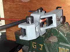
The inlet tubes were bent with the UNIVERSAL
METAL BENDER, although we don't need such
a tough tool to bend annealed copper tubes.
Copper is satisfactory for the return bend
but the stainless steel extends its life.
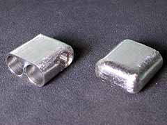
After drilling two parallel holes and a cross
hole, the block was filed down to a thin
skin.
For the return bend, the brass soldering
is better than the silver soldering. The
melting point of each material is approx.
Silver solder : 650 deg.C
Brass : 900 deg.C
Copper : 1100 deg.C
Stainless steel : 1400 deg.C
I employed 1mm brass wire as a solder, winding
it around the tubes. Applying flux freely,
the whole job was heated up quickly to a
bright red. Once you succeeded a brass soldering,
you may feel silver soldering much easy job
!
The remainders are assembled with silver
soldering. Before soldering the elbows, I
assembled whole job tentatively, positioned
the elbows and fixed them with lock screws
which would be cut off after soldering.
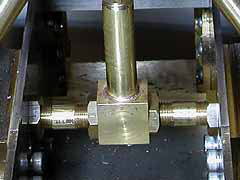 The exhaust pipes from the cylinders are
connected to the 'tee' at the center. It
looks difficult to assemble, however the
differential pitch threads make the job easier.
The exhaust pipes have totally 4 threads
(M10). The pitch of them are, from left to
right, 1.0, 0.75, 1.0, 0.75mm. The pipes
are screwed deeply into the cylinders, then
screwed back into the tee at a time. Expected
phase difference can be eliminated with the
differential pitch, moreover, with a revolution
of each pipe, the left pipe push the tee
0.25mm while the right pipe pull the tee
0.25mm. It means you can adjust the position
of the tee with the screws. After the adjustment,
each pipe is secured by the lock nuts.
The exhaust pipes from the cylinders are
connected to the 'tee' at the center. It
looks difficult to assemble, however the
differential pitch threads make the job easier.
The exhaust pipes have totally 4 threads
(M10). The pitch of them are, from left to
right, 1.0, 0.75, 1.0, 0.75mm. The pipes
are screwed deeply into the cylinders, then
screwed back into the tee at a time. Expected
phase difference can be eliminated with the
differential pitch, moreover, with a revolution
of each pipe, the left pipe push the tee
0.25mm while the right pipe pull the tee
0.25mm. It means you can adjust the position
of the tee with the screws. After the adjustment,
each pipe is secured by the lock nuts.
The blast nozzle is due to the original drawings
except additional lock nut to adjust its
height. The height was determined regarding
Martin Evans' '1:3 and 1:6 method'. Note,
a tiny blower nozzle is slightly tilt toward
the chimney.
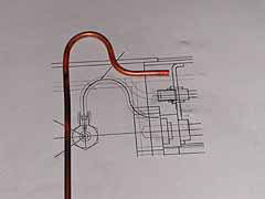
The copper tube for the blower was bent following
the CAD drawings, before cutting to a desired
length.
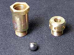
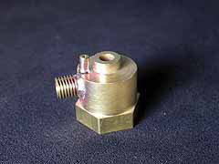
The original drawings suggest the snifting
valve mounted on the side of the smokebox.
However, to simplify the piping, I moved
it to the top of the smokebox, screwed directly
into the wet header. In this position, the
valve works 'normally open' instead of 'normally
close'. The valve seat is formed at the lower
end of the top cap. To prevent the ball falling
down, a brass pin is added, crossing the
valve body and silver soldered.
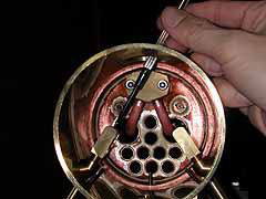
Spectacle of the smokebox piping without
the smokebox and the saddle.
| TOP | BACK | NEXT |