< Valve Gear Parts >
Due to the modification from s.v. to p.v.,
the radius rod tilted at mid position. Therefore
the lifting arm pivot was deviated from center
line of the radius rod. As a result the stroke
of the arm became asymmetric. So I shifted
center of the reversing arm to compensate
the asymmetry.
Valve gear components have complicated shape.
The process of cutting is similar to the
connecting rods. I prepared a common jig
for them so as to save time. The process
is as follows.
![]()
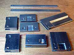
BMS blanks for the valve gear.
![]()
Connecting holes were drilled and reamed
on the blank and the jig at a time. Finally
the jig has one common hole and many different
holes for each component of the valve gear.
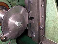
If required, slits at the both end were cut
with a thick slitting saw.
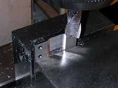
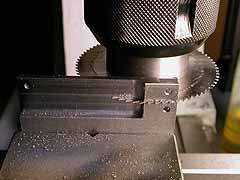
The side recess is end-milled. To prevent
chattering, the cutter is moved "down"
at first.
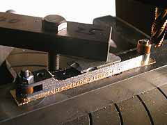
The side profile is finished. Note large
excess part for chucking in machine vice.
The excess part were cut out with a thin
slitting saw.
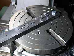
The drawing shows valve gear components on
the jig. The jig is fixed on a rotary table
precisely aligning its center pin (black
circle) to the table center. Each blank is
hold with the center pin and another removable
pin in suitable hole in the jig.
Account for each component...
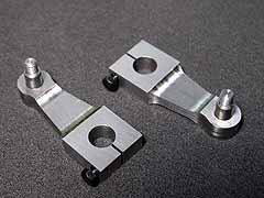
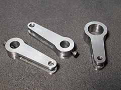 [Lifting arms & Reversing arm] Slit of the lifting arm is very deep. Therefore it was finished with drill and end mill. |
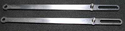 [Radius rods] The profile is tapered before the pin and parallel after the pin. The slit at the rear part is slot-drilled. The pin was press-fitted. |
|
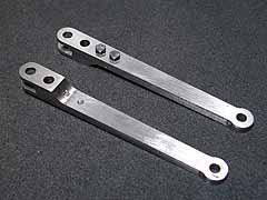 [Combination levers] Cutting deep recess resulted serious bending of the material. The correction was done by clamping on a flat plate and heating to a bright red with the plate. |
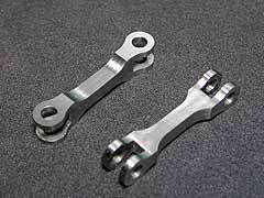 [Anchor links] Most tiny and complicated parts. |
|
 [Return cranks] The rectangle shape was cut by moving X and Y axis of the stage. The bottom is slotted and will be tightened around the crank pin with a small screw. Finally a taper pin will be used so as to prevent rotating. |
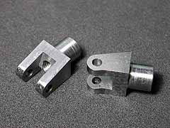 [Valve crossheads] After turning the bush part with independent chuck, The slotted part was finished in the rotary table. I used a square bar with a reamed hole so as to chuck the bush part firmly. |
The eccentric rods will be made after assembling
the valve gear. Because the length of them
should be taken from the job.
| TOP | BACK | NEXT |