< Casting Pattern Making >
In the last few months, I have gathered photographs,
drawings and documents of the prototype.
Then I found several mistakes in my plans.
So I corrected 3D plans as follows.
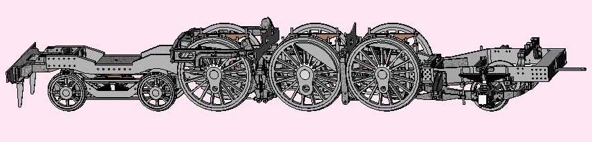
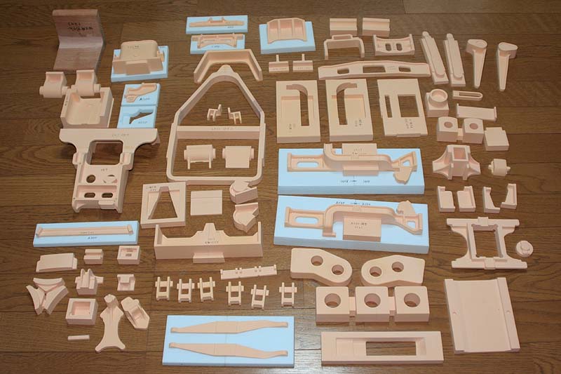
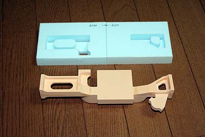
On the other hand, I have been making wood
patterns for castings with MODELA, and then
all of the patterns for castings in the 3D
picture were completed.
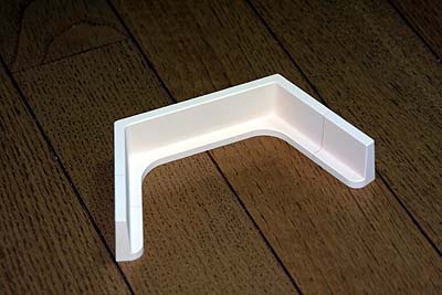
Chemical wood is too expensive to use freely.
So I put together small remains of material
before cutting large patterns by MODELA.
The photo is an example.
 |
The picture shows several kinds of sand casting
methods. And the followings are examples.
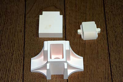
[Method 1] Trailing axlebox assy
Most simple pattern with flat bottom.
[Method 2] Front buffer casting
Divided patterns that have pairs of location
holes and pins. I employed 3mm banboo needle
for the pins.
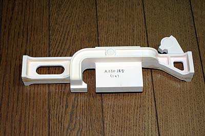
[Method 3] Trailing equalizing arm
If the pattern cannot be divided, it needs
a pedestal between the base line and the
parting line. The pedestal also can be made
directly from sand when casting.
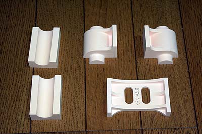
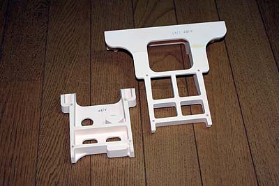
[Method 4] Brake cylinder
Divided patterns with corebox to make a cavity in the casting. Incidentally,
the lower right one is a stretcher to hold the brake cylinder.
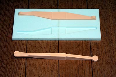
[Method 5] Motion plate
The picture shows casting result. It has
a cavity and cannot be divided. Therefore
the pattern needs core and pedestal.
The pattern has wide rectangle coreprints
to hold the long core. Note the corebox has
recess for the coreprints.
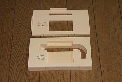
Reversed pattern and the pedestal. The pedestal
covers the pattern up to the parting line.
The pedestal is made from urethane foam,
that is test cutting material for MODELA.

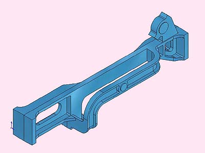
All of patterns, cores and pedestals need
'draft'. The picture shows direction of the
draft. They are reversed at the parting line,
not at the base line. This time the draft
angle is 1.5 - 3 degrees. Also I made all
patterns x1.01 bigger than the plans, due
to expected shrinkage.
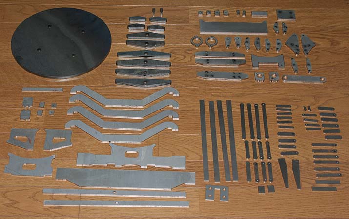
I ordered additional laser-cut plates. They
are made of 2, 3.2, 4.5 and 9mm thickness
steel sheets. They are not only the loco's
components but also working jigs. For example,
the large disk at upper left is an extension
of the lathe's face plate.