< Start Erection of Frames >
[Slotting Attachment]
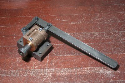
Key seat cutting will be necessary in future
for driving and coupling wheels. So I prepared
lathe slotting attachment that makes it easier.
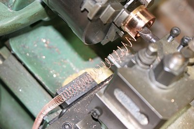
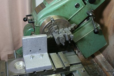
I utilized cylinder block casting reservoir
for the William. Key seat cutting tool is
hold in a stem. The stem moves to and fro
through bushes at each end of the casting's
bore. To ensure precise key-cutting, the
stem and the bushes have to be finished very
close fit.
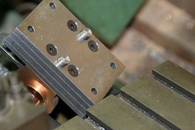
The steel base stack is to raise the casting
to the lathe center height. Note two pins
under the base stack. The pin's diameter
is equal to the lathe cross-slider's groove
width. They make the unit always parallel
to the lathe headstock. For that purpose,
we should do boring of the casting after
securing the unit with the pins.
The boring tool is that I made for William's
cylinder boring, with a tip made from old
HSS drill.
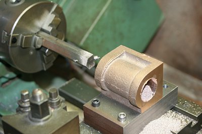
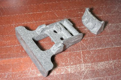
The phosphoric bronze bar that I used for
bushes was terrible material. Its elastic
character captures drill as if it is press-fitted
into the material. The photo shows before
and after cutting. Material color changed
reddish by high temperature in cutting.
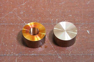
Inner and outer diameter of the bushes should
be finished at a time, so as to ensure true
concentricity.
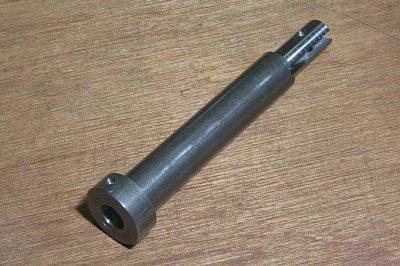
The stem is made from silver steel round
bar. The slit is cut with metal saw. The
stem has a clean hole at the center to hold
cutting tool. The hole is opened with drill
and finished with small boring bar. Also
a cross screw hole is opened in the collar
glued on the stem. It is for a screw to secure
cutting tool.
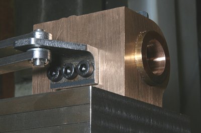
The link is made from bright mild steel bars.
The bracket is made from ground steel angle.
In the picture, the link is fixed with pins
and E-rings. But I replaced them with bolts
and nuts, in order to make the linkage tight.
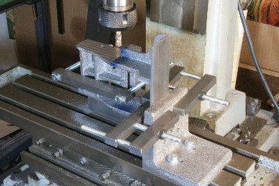
[Angle Plates]
I received several castings from a foundry's
engineer. First I finished 100 mm angle plates
which will be vital for many works. Mount
on the lathe cross table and fly-cut each
square face. The fly-cutter is a knife tool
in the tool post which is hold in four-jaw
chuck.
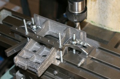
[Truing Up of axlebox slit]
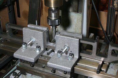
The main frame thickness is 12mm, so hornblock
is not necessary. But laser-cut section is
wild and tapered, so I trued up the section
with end mill. I utilized four of the 100
mm angle plates to hold the pair of frames
rigidly. The end mill's diameter is 21 mm.
The slit depth is 60 mm. It is beyond the
capacity of my milling machine. Therefore
I cut every 5 mm depth until the bottom.
Finally, I cleaned the cutting face with
an oil stone.
The main frames material is cold (bright)
steel bar. Its residual stress caused me
a great deal of trouble. First I tried to
true up top edge of the frames. I cut only
0.2 mm surface, then the top edge warped
convexly (left hand picture). After that
I trued up the axlebox slit. When I released
the chuck after cutting, the slit was deformed
in bell-bottom shape, on the other hand the
frames' warp disappeared (center picture).
So I had to do truing up again (right hand
picture). As a result, I got 0.2 mm wider
slit than I designed.
I think laser cutting edge includes tensile
force, while the inside material includes
compressive force. If we remove the edge,
then the material extends immediately. We
should better ask local factory to anneal
whole job before any cutting.
The hornstays are laser-cut, too. Before
fix them on the frames, bolting face is cleaned
by endmill. Opposite face in the frame is
also cleaned.
All of stretchers and buffers between the
frames are made of cast iron. First of all,
front and back end castings are built on,
so as to join both frames. The picture shows
those castings. The bigger and complicated
one is front buffer casting.
[Front buffer casting]
I have to cut front, top, bottom, and side
faces. Width of the casting is around 200
mm. Only X-axis of my milling machine can
cut this length. The photo shows cutting
top and front faces. After that, the job
was reversed and top face was cut.
The photo shows cutting side faces. First,
two angle plated are fixed on the machine
stage truly square in each. Then top and
front faces of the casting are push against
the two faces of angle plates, and secured
with suitable clamps. Then the side face
can be cut truly square to both front and
top faces.
[Rear stretcher casting]
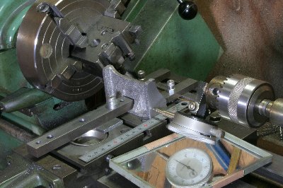
The casting is enough small to handle in
the lathe. First, the bottom face was turned
in four-jaw chuck. Then each side face was
fly-cut as the photo shows. Note a DTI in
the tail stock that was to cut each side
face truly parallel.
[Main frame twisting]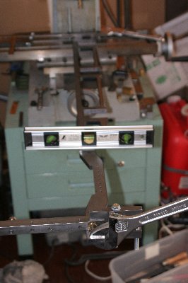
I checked the main frames again and found
that one of them was slightly twisted. Then
I tried to true it up again. I fixed the
rear end on milling machine's table, held
the other end with large clampers, and then
gave an opposite twist to the frame. After
many times of powerful motions, the twist
was disappeared.
[Combination of two frames]
Mark out one hole in each side of a casting,
punch, drill and tap them. Then build on
the casting between frames with one screw
in each side. Adjust angle of the casting
on a flat surface, and clamp them. The photo
shows how to make the front face of the casting
square to the main frames. For this operation,
I utilized combination of straight and square
rules.
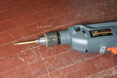
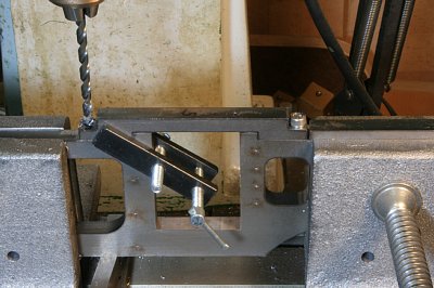
Then counter sink the casting through all
of holes in the frames. The photo shows a
portable hand drill that I used. Note a brass
tube around the drill bit as 'stopper'. After
that, disassemble, drill and tap the rest
of holes.
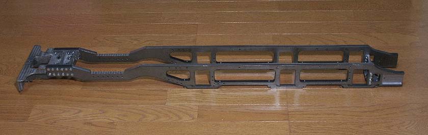
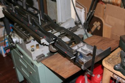
Reassembled main frames. The whole length
is around 1 meter. Rear frames of 0.5 meter
length will be bolted on them.