< Rear Side Frames >
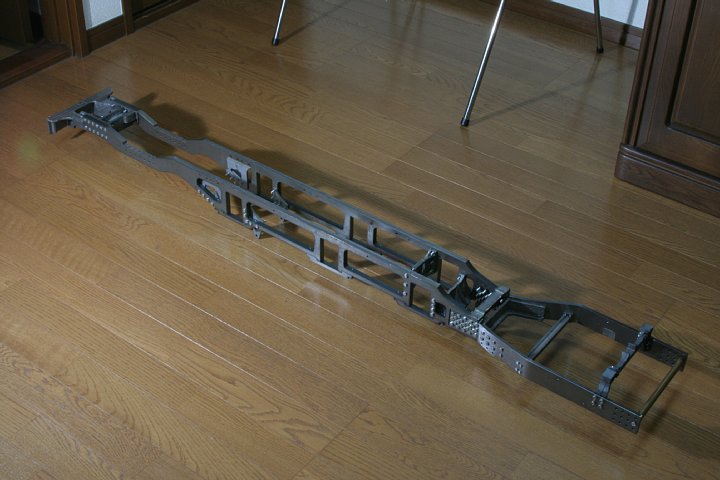
The rear side frames were laser-cut and bent
from 6 mm steel plate, by a local factory.
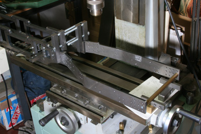
To attach them onto the main frames precisely,
I employed milling machine's stage as a flat
surface. The main frames are bolted down
onto the stage. Front ends of the rear side
frames are fixed to the main frames with
two screws. Back ends of them are combined
each other with a round brass bar. Suitable
packing under the bar holds the rear side
frames in a desired height. Then main and
rear side frames are clamped firmly.
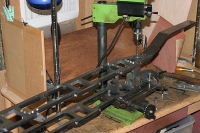
Drill the main frames through holes of the
rear side frames. For this operation, I used
small milling machine. Such a tiny machine
is sometimes more useful for huge job.
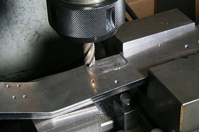
A recess of 1.5 mm depth was cut from inside
face of the each frame. It is a trick to
increase swinging degree of the trailing
truck, so as to clear 7.5 meter radius track
layout.
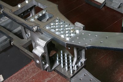
Two castings, front expansion bracket and
trailing truck pivot pin bracket, are mounted.
All of side faces are milled as same as the
other castings.
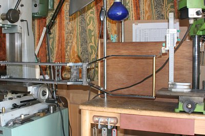
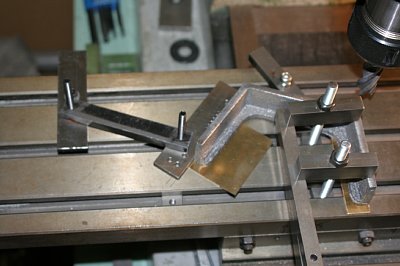
Here I adjusted the broadening degree of
the rear side frames to be symmetric. The
photo shows how to do this with milling machine's
stage as a flat surface and a height gauge.
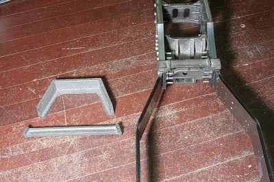
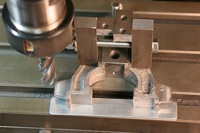
The picture shows frame reinforcement castings.
They have two side faces broadened along
the rear side frames. These faces have to
be machined precisely.
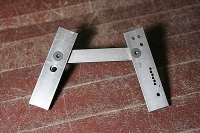
I made a jig from steel bars that can trace
the taper of the rear side frames. After
cutting one side of a casting, the jig is
applied to align another side perpendicular
to the stage.
Align and clamp the castings, countersink
in the castings through the holes in the
frames, disassemble, drill and tap at the
countersinks.
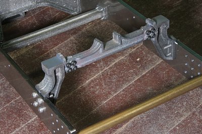
The rear expansion bracket consists of three
castings, two side castings and one center
casting. First the side castings are machined
and bolted onto the frame, and then the center
casting is aligned and bolted.
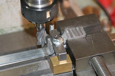
The photos show how to machine the side castings.
It has three flat faces perpendicular to
each other. The left hand photo shows cutting
two faces at a time. The right hand photo
shows cutting the last face. Note the tricky
clamping because the castings have complicated
shape.
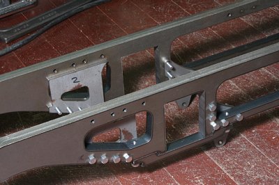
Two kinds of laser-cut parts are bolted onto
the main frames.
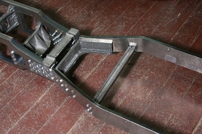
Assembled chassis. It is two times longer
than the William. Moreover the tender will
follow it.