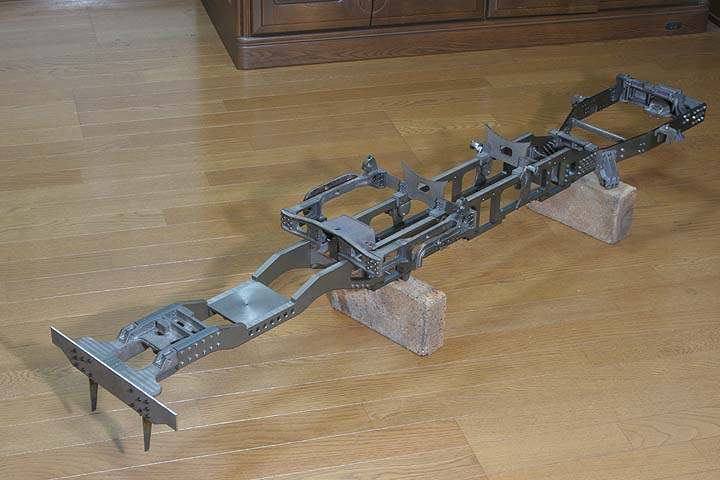
< Complete Chassis >
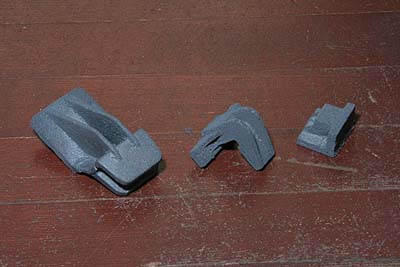
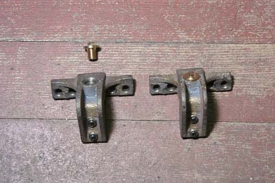
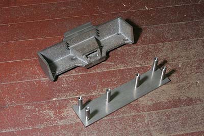
The photo shows casting parts for the trailing
frames, from left to right, back equalizer
bracket, trailing spring support and equalizer
end bracket. The first two types were cast
with cores so as to mold entire shape. The
last type is too small to cast with core.
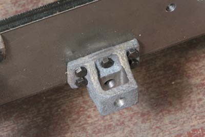
I started with the back equalizer brackets.
After cutting the bolting face, both sides
of the slit are milled to a desired width.
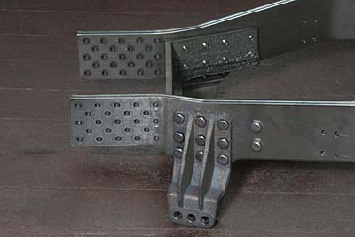
There are nine holes for bolts. First I opened
the central one hole and fixed the casting
to the frame. And then drill through the
rest eight holes from the frame. Six bolts
of them also fix the reinforcement casting
in opposite side.
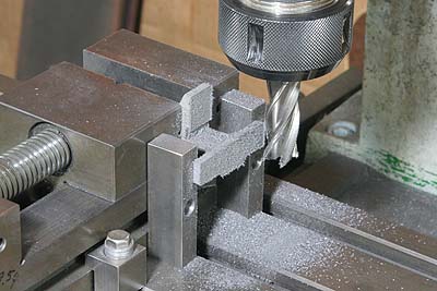
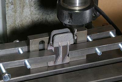
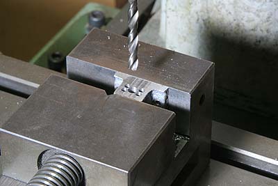
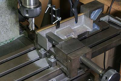
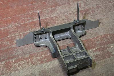
Next is the trailing spring supports. As
the photo shows, two faces were cut by end
mill in a time. Note two steel bars to avoid
slipping of the job in cutting.
I made dummy oil pots from round brass bar
and screwed them down into the castings.
The studs and nuts are also dummy parts.
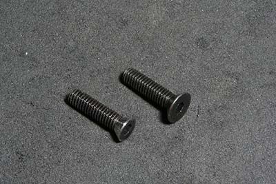
In case of the prototype, the spring supports
are fixed by hammer bolts which have steep
countersunk heads with no recess. I modified
a kind of countersunk screw turning its head
angle from 90 to 60 degree.
For the modified screws, I made a countersink
cutter from a drill rod. It was hardened
with propane gas torch but tempered with
electric furnace, rising temperature to 230
centigrade and cooling immediately. Electric
furnace makes such heat treatment much easier.
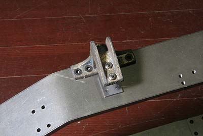
The casting was bolted onto the trailing
frames. The plate under the bracket is slipping
plate for laminated leaf springs.
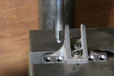
The equalizer end casting has no hole, so
I opened square hole. First I drilled four
corner and center holes. After that I opened
it to square profile by end mill and files.
The bracket was mounted to the frames.
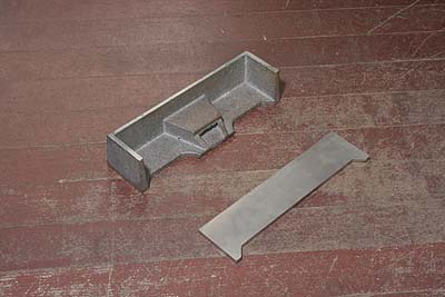
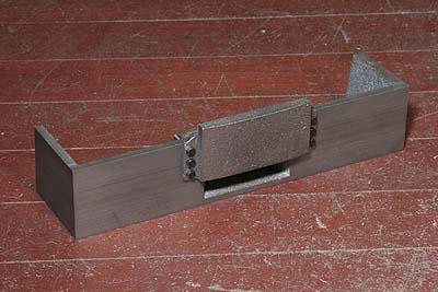
The photo shows rear frame casting that closes
the trailing frames at their ends. That of
the prototype is one body casting. But I
separated top plate so as to ease casting.
The tunnel at center bottom of the casting
is coupler pocket.
First I finished the bottom face, and then
I cut back and both side faces.
The top plate has six studs to fix itself
onto the bottom casting. Against the studs,
shallow recesses were cut on the casting,
in order to make height of the studs even.
The casting plate on the back side is tender
buffer catcher.
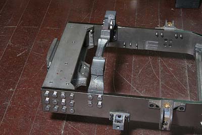
The main frames and trailing frames were
connected again. And the rear frame casting
was secured between the trailing frames.
Again I checked out rear frames' height and
symmetry during the assembly.
Coming back to the main frames, front butter
beam, front bottom plate and the pilots were
put on the front frame casting. All of them
are laser-cut parts.
The chassis was completed.