< Leading & Trailing Wheels >

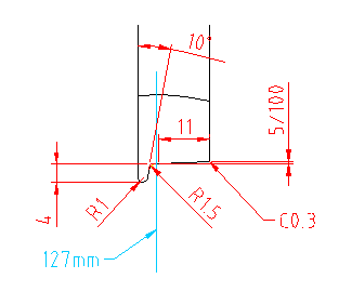
Before cutting wheel castings, I have to
determine the wheel contour. There are two
major track standards in Japan. One is OS
standard with 119mm back-to-back and the
other is Modelnics' 117mm back-to-back. It
is difficult to make a loco which can safely
pass though both two kinds of turnouts. The
drawing shows determined wheel contour. To
attain the purpose, the back-to-back is 119mm
and the flange was designed as thin as the
strength permits, on condition that the castings
are made of ductile cast iron.
I started with six wheels for leading and
trailing trucks. First, in four-jaw, backside
of the wheel was faced off and the center
hole (19mm) was opened with drill and boring
tool. After that, back recess among the spokes
was cut by a roundnose tool.
Here I prepared a wheel cutting jig modifying
the jig for William's driving wheel. Once
you trued up the jig's outer front face and
the spigot, you cannot release the jig until
you complete all of operations for the wheels.
In the jig, the wheel was first chucked by
screws between the spokes, and then the boss
was cut outward from the center with a boring
tool.
The screws were replaced with short pins
and the wheel was fixed with a disc on the
boss. Then the rim surface and step were
cut.
So as to finish the wheel contour precisely,
I calculated coordinates of the tool tip
and moved the tool in 0.1-0.2mm step. After
that I removed micro notches by a fine round
file.
I found unacceptable blowhole on the tread
of a wheel. So I have to cut one more wheel.
I have no choice but to release the jig halfway.
To minimize the error, I released the jig
together with the three-jaw chuck. Then the
error was only 0.01mm. Anyway the best method
is preparing one more casting from the beginning.
1/20 tapered tread was cut by adjusting the
top slider's angle.
They are finished wheels. The left four are
for the leading track, while the right two
are for the trailing truck. This time I did
grinding the wheels with emery cloth, so
as to proof against rust.