< Equalizing System 2 >

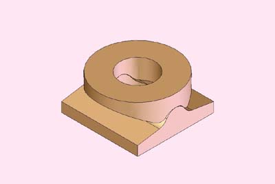
There are engaged washers at both ends of
the leaf springs. Upper and lower washers
are engaged with round surface, so as to
make it possible to swing. The engine needs
24 pairs of the washers, including the leading
truck. I prepared home made cutters to mass-produce
the washers.
The cutters are made from 10 mm carbon steel
rod. The photo shows turning the cutter blank
with a home made roundnose tool. The cutter's
section was drawn in CAD and calculated to
a coordinate table in 0.1 mm pitch. Then
the tool was inched according to the table.
Finally the cutter was ground with fine files.
After milling the recess for blades, the
cutters were hardened by propane torch and
tempered in electric furnace. Then the blades
were ground with oil stone. I need two cutters
for upper and lower washers.
I started with the upper washer. In the lathe,
a brass round bar is drilled in a desired
depth. Then the job is transferred into a
machine vise on a milling machine and cut
section of the engaging side by the above
cutter (photo). Finally it is parted off
in the lathe.
The lower washer is made from a brass rectangle
bar, so it is started in four-jaw. Procedure
is the same as for the upper washer, except
forming a projection in back side with a
parting tool just before parting off. The
projection is for press-fitting.
The lower washer is press fitted into the
top spring and soft soldered for reinforcement.
The photo shows reassembled leaf springs.
The bottom one is a washer for the trailing
equalizer. It was made from round bar and
has long projection. The projection was glued
into the casting with Loctite, because cast
iron is difficult to soft solder.
The photo shows laser-cut links crossing
over the main frames. I just drilled holes
in precise distance.
Pins for the links were turned from steel
round bar. They are fixed with washers and
small cotter pins. The pin's diameter is
1 mm.
The trailing spring holds a slipping disk
against the axlebox of the trailing truck.
The disk is made from cast iron with gunmetal
slipping ring. Note the recess around the
hole, so as to hang the disk with a bolt
from the bottom.
The square piece above the disk has screwed
hole for adjusting projection of the bolt.
The bolt is adjusted to let the disk swing
freely.
The equalizing system was completed. I was
tired from making many kinds of mass productions...
The photo shows close-up of the engaged washers.
The double nuts adjust the engine height.
Only the last pair of washers is fixed with
a cotter, instead of nuts.
Two dummy bolts are fixed nearby both sides
of the spring saddle. The bolts jam the saddle
between their heads.