< Equalizing System 1 >
The drawing shows equalizing system of the
loco. Three driving wheels and trailing wheels
are linked together in each side.
Each equalizer beam between driving wheels
swings in a cutout of the main frames. It
can tilt until its end touch the upper frame
of the window. That is to say it determines
limit of the equalizing motion. I calculated
the maximum gradient that the equalizer can
pursue. The chart shows equalizer motion
when the middle driving wheel passes a sharp
valley. Red point shows each wheel's position,
from left, leading - three driving - trailing
wheels. The blue lines show equalizer motion
and the green line shows tilt of the loco
body. If you reverse the chart vertically,
you can get a motion when the loco passes
a sharp summit.
From calculation, the maximum gradient is
about 6.5 per million (13 per million from
downhill to uphill) in both at valley and
summit. As actual gradient always changes
smoothly, the equalizer can follow typical
ground level track layout with maximum 10
per million slopes. Incidentally, even if
the gradient reaches to the limit, any wheel
does not rise from the track, because the
axlebox can drop independently. Only the
axle weights become uneven.
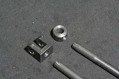
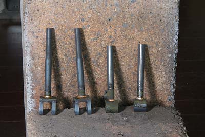
I started with the spring shafts. There are
two types, eye bolt type and fork end type.
The former is made from 5 mm and 10 mm silver
steel round rods screwed together and silver
soldered. It is difficult to pour solder
into the thread, so I cut a groove crossing
the thread by a fine triangle file.
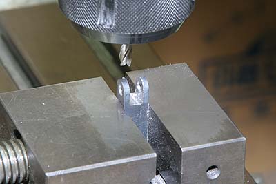
The fork end type was made from laser cut
square rod. Note the rod was enough long
to chuck in a vise while cutting the slit.
After that the chucking part was cut off
and threaded to connect the shaft.
The parts were degreased with spirits, screwed
together with flux. Silver solder rings were
prepared by coiling a fine silver solder
wire and cutting by wire cutter. The rings
were put around the shafts, then whole job
was heated by propane torch. Surplus solder
melted down into the hole was removed with
a leamer.
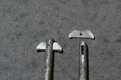
There is a kind of spring shafts that will
be fixed to the leaf spring with a cotter,
instead of double nuts. I cut a long hole
in the side of the rod by 2 mm end mill.
The cotter was made from 2 mm steel plate.
Cotter and shaft have small holes to bind
with a pin.
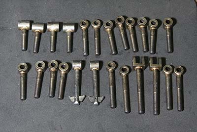
There are 24 shafts for the engine including
4 for the leading truck.
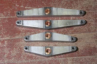
Each equalizer beam for driving wheels was
laser cut from 9 mm steel plate. A phosphor
bronze bush was press fit. The bush is not
vital for such kind of parts. But it can
space the beam from inside faces of a bracket.
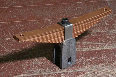
The picture shows driving wheel spring with
a saddle. The saddle rides the main frame
astride and pushes the driving axlebox by
its feet. The saddle is cast irons with large
bottom slits and small rectangle windows.
In case of full size locomotive, the leaf
springs and the saddles are individual parts.
But I combined them so as not to let them
fall apart when carrying the locomotive.
Top of the casting was cut to a width of
the spring holder, and a screw hole to secure
the spring was opened.
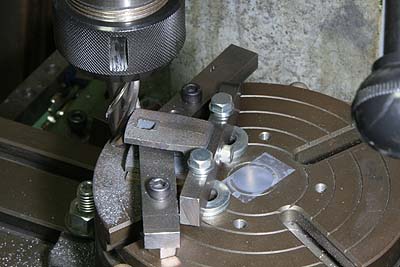
The saddle will be swung according to the
equalizer motion. So its bottom line should
be curved. I cut it on a rotary table. Incidentally,
center of the radius corresponds to a middle
point of the spring top face. It is to balance
fall down force and stabilizing force.
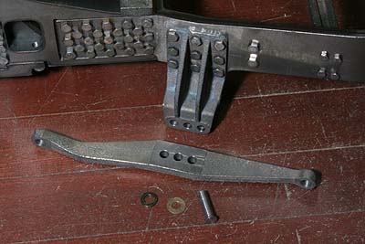
The trailing equalizer is cast iron made.
The three holes for the fulcrum are same
as prototype. They are for adjusting axle
weight of the trailing wheel. Incidentally,
if you change the trailing axle weight by
this fulcrum, the leading axle weight is
also changed automatically.
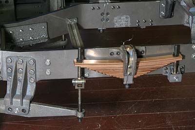
I temporary assembled the trailing equalizer.
Swing washers are missing between the spring
and the nut. I will introduce in the next
issue.