< Driving Wheel Assembly 1 >
Full scale driving wheel is secured on axle
with rectangle "key". After that,
quartering is done with "Quartering
machine" that can bore crankpin hole
or turn crankpin O.D. at desired radius and
angle from the axle center. I employ similar
procedure. Crankpin holes will be opened
before assembly. And then, the wheels will
be put on an axle with keys. Finally, I measure
quartering error and prepare 'eccentric'
crankpins that can compensate the error.
Anyway, the crankpin hole should be opened
in correct position as much as possible.
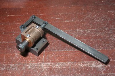
Key way in a wheel is cut by "Slotter".
I had already made a hand slotter on Feb.2007. So I prepare a cutter for the tool.
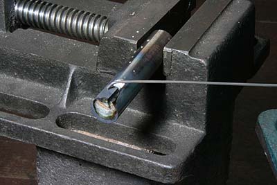
I utilized 5 mm square tool bit of high speed
steel for the cutter. It was broken in a
desired length and silver soldered into groove
of a steel round bar. Note a hard stainless
steel wire secures the bit in the groove.
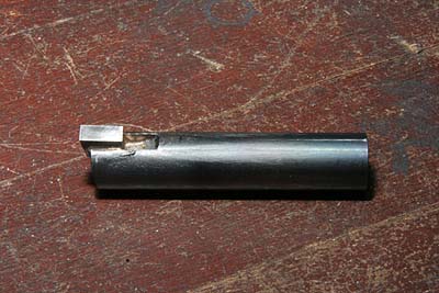
The cutter was finished with grinder and
oil stone.
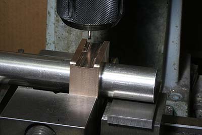
After clamping the wheel on the extended
face plate, the center spigot is driven out.
Then, the face plate is locked in suitable
angle with a wood block between the saddle
and the faceplate. After that the key way
is cut by the tool. It was cut to 1.5 mm
depth with 0.05 mm step inching.
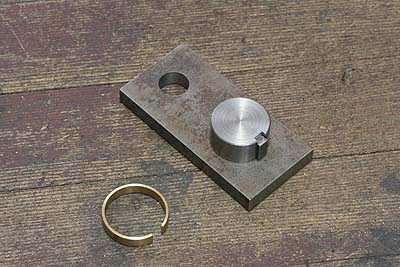
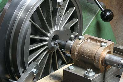
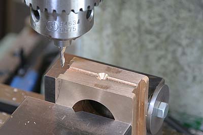
The crankpin hole should be opened in true
radius from the axle center and in truly
opposite from the key position. To do this,
I prepared a drilling jig like the photo.
The hole's diameter is 12.9 mm. The brass
C-shape ring is for adjusting diameter of
the axle, because the 2nd driving axle is
larger than the 1st and 3rd axles.
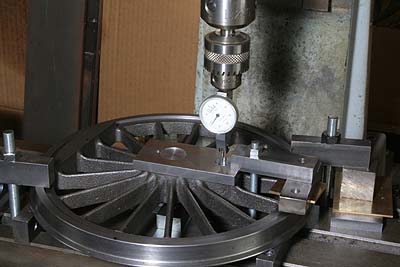
Due to diameter error of the wheel center
hole, the jig sometimes has minute play in
angle. In such cases, I measured the play
with DTI, found midpoint of the play and
fixed the jig at the point. After that, I
drilled 12.9 mm through the jig and reamed
to 13.0 mm without the jig.
Here I make axleboxes. They are made from
gunmetal castings. In the lathe, I finished
the bottom face, turned over, finished top
face and center hole.
The top face was finished first. Note a round
bar determine height from the hole. After
that, the bottom face was finished.
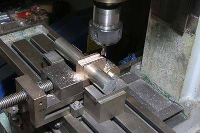
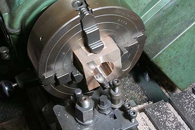
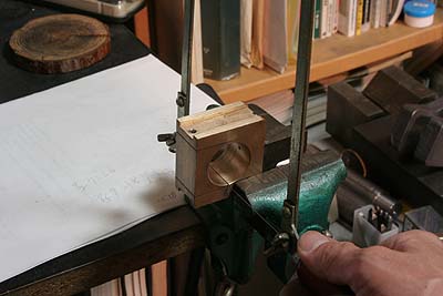
The photo shows how to cut the side grooves
of the axlebox symmetrically. A dummy axle
is passed through the axlebox and is supported
by a pair of blocks at both ends. Then the
axlebox is chuck in a vise. After finishing
one side, the job is turned over and chucked
again. Thus the both grooves can be cut in
the same distance from the axle center.
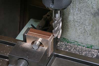
So as to allow the axlebox to roll in the
frame, the groove was extended to X-shape.
To do this, the vise was leaned +/- 3 degrees
from square. Incidentally, full size axlebox
cannot roll in the frame. The axle itself
rolls in the axlebox.
Channel for lubrication was cut. It consists
of longitudinal groove and center hole with
CSK. When practice, I drop oil on the axlebox
through spokes of the wheel. And then axle
and side grooves are lubricated at the same
time.
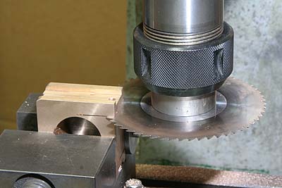
In order to ease maintenance, I split the
axlebox. First, horizontal hole for secure
pin was drilled and reamed just under the
axle hole. Next, two vertical slits were
cut from the bottom with 0.5 mm slitting
saw.
Finally horizontal slits from the axle hole
were cut with a fret saw. Then the axlebox
is separated.
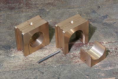
The photo shows completed axleboxes with
secure pins. 0.5 mm gap is left after assembly.
But it is no problem because the lower part
is exactly located by the pin and the axle
itself. Moreover the axle weight always loads
on upper semicircle of the hole.