< Valve Liner 1 >
Before assembling the cylinders, I fixed
the cylinder block onto the chassis temporary.
A horizontal concavity under the cylinder
block fits into a vertical concavity on the
chassis, only it has a little play.

A stretcher over the bogie truck is once
removed from the chassis and drilled for
screws.
![]()
The stretcher is fixed in the chassis again,
the cylinder block is positioned, then the
cylinder block is drilled through proper
two holes. After that both parts are removed
and combined with pins. Finally the rest
of holes are opened. The cylinder block has
tapped holes. It means the screws are put
in from underneath.
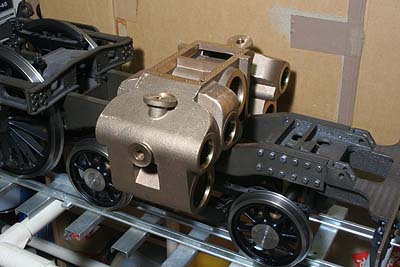
The cylinder block is temporary fixed. Incidentally,
the prototype doesn't have such a stretcher.
The cylinder block is directly bolted onto
the chassis. The bolts are put from inside
to outside. Also the cylinder block holds
the bogie truck directly. In the model, I
employed the stretcher so as to ease assembly.
Following the prototype, I chose piston valve
for the engine. My first engine William has
piston valves without piston rings. This
time I want to use piston rings because the
model is very big. So the valve liner must
have lines of holes in circumference for
the steam ports. I started with the liners.
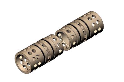
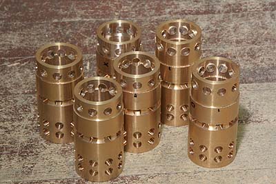
I designed the valve liner divided in front
and back pieces. It needs six pieces for
the three cylinders. The inner liner is longer
than the outer liners. Middle section (steam
inlet section) of a pair is called "basket".
That's only spacing the outer working section.
Both I.D. and O.D of the basket don't need
to be precise. I utilize the basket as a
chucking part for cutting the outer working
section. That's the reason why I divided
the liners. From outside to inside, the lines
of holes are for steam outlet, steam port
and steam inlet. The steam port holes must
be rectangle.
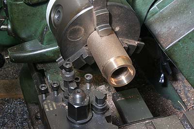
If I made the liner from a round bar, I must
cut plenty of metal to bore a large tunnel.
So I prepared cylindrical castings in gunmetal.
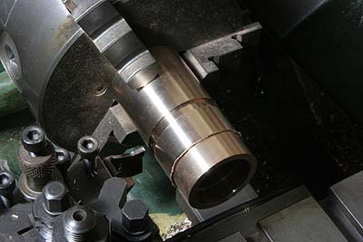
First, the basket section is cut. It has
smaller O.D. and larger I.D. than the working
section.
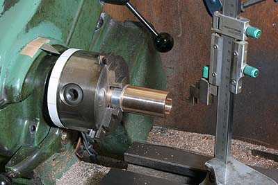
Reversed and chucked in the basket, the working
section is temporary finished. Next, I divided
the circle and scribe radial lines in the
lathe. Note a paper band around the three-jaw
and an indicator on the headstock so as to
divide the circle in equal angle.
The job is reversed again and a guide groove
for the steam port is cut.
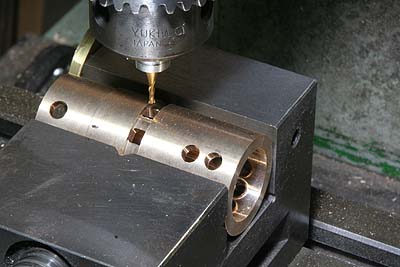
The liner is clamped in the machine vise
in desired angle by the radial lines. Then
the four holes are opened. The hole for steam
port is drilled and cut rectangle by 2mm
end mill. Tiny fillets remain in four corners,
but they can be removed easily with a fine
rectangle file. Totally I have to open 60
rectangle holes and 180 round holes!
I spent two weeks for the operation. Here
I reach the time limit of the report.