< Side Rods 1 >
The next step is side rods. In the drawings, the left one shows front side
rod and the right one shows back side rod. The red circles are crank pin
bushes. Front and back side rods are connected just before the second crank
pin.
Connection of the side rods is 'knuckle-joint'. The front is 'fork' and
the back is 'eye'. Both are connected with a countersunk pin and double
nuts.
I asked laser-cut parts cut from 12 mm black mild steel bar.
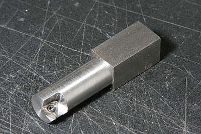
Required holes in the side rod are comparatively large and I don't have such large drill. So I made a boring bar that holds throw-away tip and is held by four-jaw chuck.
Finally the wheelbase will be taken from the crank pins. But I started with designed distance. Because the material will be possibly extended during the cutting process. Therefore, at the moment, the first and the third crank pin holes are drilled smaller than the final size.
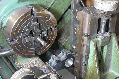
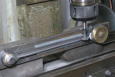
The photo shows set up for boring with vertical slider in the lathe. The second crank pin holes are 24 mm dia. I cut them with the boring bar. The other holes are drilled and reamed.
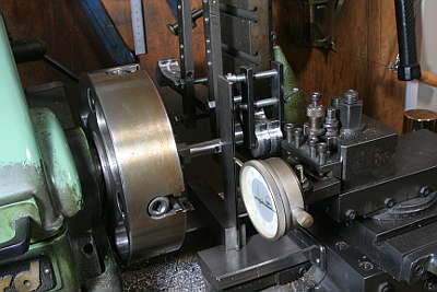
The boring bar's stroke is adjusted with a dial gauge set in the lathe cross slider.
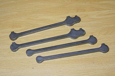
Eyes of the back rods are cut.
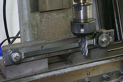
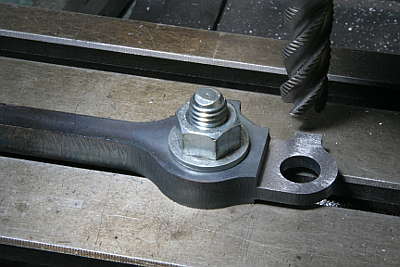
In order to cut intermediate part of the rods, I prepared side cutting jig from a flat bar and angle plates. I started with rough-cut end mill and finished with plane end mill.
First I cut both ends of the thin part to final depth by front face of the end mill, in order to avoid chattering.
Fork of the front rod is cut. First I drilled round bottom and cut both sides with a metal saw.
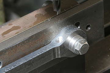
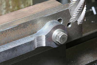
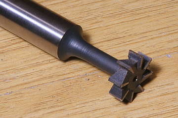
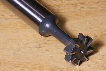
The flute of the rod is generally cut by wood-ruff cutter. The result is parallel and square flute. But full size locomotive flute has squeezed ends. So I modified the cutter.
The shape of flute end depends on cutter profile, cutter diameter and flute depth. In this case, cutter diameter is 16 mm, flute depth is 1.2 mm, and the cutter has 1 mm radius rounded edge. The red line of the drawings shows point of 1 mm depth. From here, the flute width starts squeezing. At the end of the flute, the flute depth become zero, so the flute width becomes 2 mm smaller than the start.
I asked a local tool repolishing shop to modify my cutter. The photos show before and after modification. Note the left one has squared edges, while the right one has rounded edges.
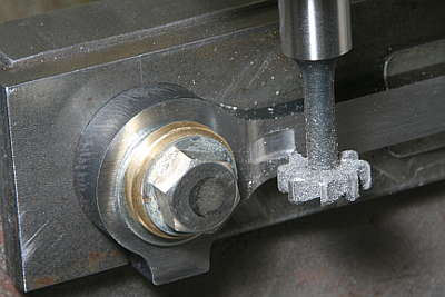
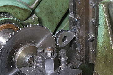
The flute is cut with the same setup as the side cutting. I also started from both ends to desired depth. Here I had terrible chattering, so I stopped the head motor and rotate the head by hand.
The flute width is 6 mm but the cutter width is 5 mm. First I cut along the center line. After that the tool was shifted 0.5 mm upper and lower. The full size side rod has flutes on both sides, but I cut only on the outside.