< Side Rods 2 >
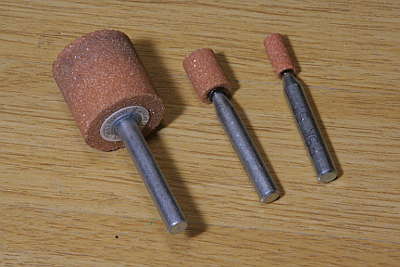
Laser cut cross-section is cleaned up with grinding stones. I prepared
6, 10, 25 mm radius stones. Larger radius stone is more effective but cannot
grind smaller recess.
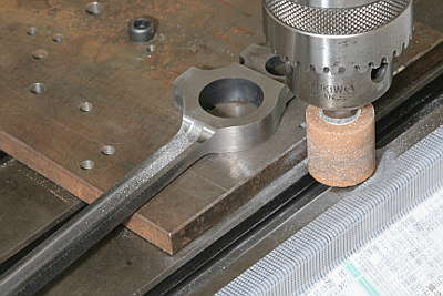
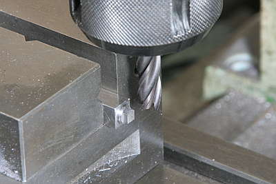
I utilized milling machine for grinding with its top speed. But it took a full day to clean up four side rods.
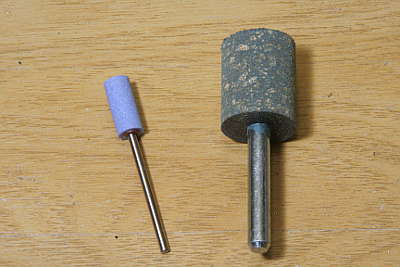
I employed #60 stones for grinding but its finish is not smooth. So I added #120 stones for polishing. These numbers show fineness of the stones.
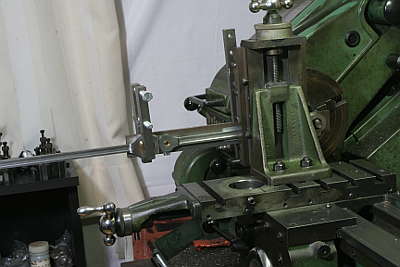
Having finished all of cutting works, the wheelbase of the rods are determined.
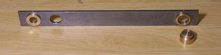
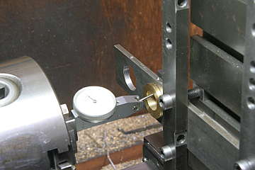
The photo shows a jig to take wheelbase from the crank pins. It has three
holes because front and rear wheelbases of the three axles are different.
Each wheelbase from the second crank pin (19 mm dia.) to the first or the
third crank pin (14 mm dia.) is taken. I made an eccentric bush for both
the first and the third crank pin eccentric 0.5 mm to the center in order
to adjust wheelbase. Also the second hole has a concentric bush in order
to secure precise hole by turning in the lathe. The jig has set screws
in it for locking the bushes. The step plug in the photo is for centering
smaller jig's hole and larger rod's hole.
Before taking the wheelbase, the crank pins are lined up to the dead center by desired length of brass bars.
Put the eccentric bush into the crank pin. Rotate the bush and fit it into the jig. Then lock the bush with the set screw. It should be the same result at both front and back dead centers.
Starting with the rear wheelbase. It is finished as follows.
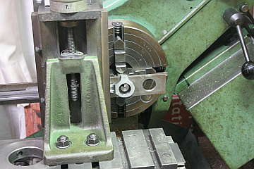
1. Place the jig on the rear rod with centering the concentric bush to the second crank pin hole in the rod.
2. Clamp the whole job on the vertical slider and align the eccentric bush to the lathe center with a dial gauge.
3. Release the eccentric bush and finish the third crank pin hole of the rod through the jig hole.
In case of the front wheelbase, it is determined by both front and rear rods. They are lined up and bolted together, then done the same operation as the rear wheelbase.
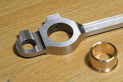
Bushes for the rods are made from gunmetal round bar. I took 0.1 mm play in diameter for each crank pin. Before fitting the bush, surface of the rod ends are polished by emery cloth put on a flat face.
The bushes are press-fit into the rods. Outer diameter of the bush is finished 1/300 smaller than the hole diameter. Note the center hole of the bush will also become smaller after the press-fit.
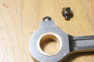
Dummy oil pots are screwed into the rod.
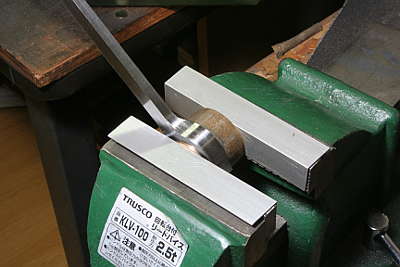
Plug of the oil pot has square head. I utilized a rectangle bar as a dividing head. First the plug's thread part is cut and screwed into the rectangle bar. Then the bar is chucked at the bottom of the vise and cut each square faces by rotating the bar.
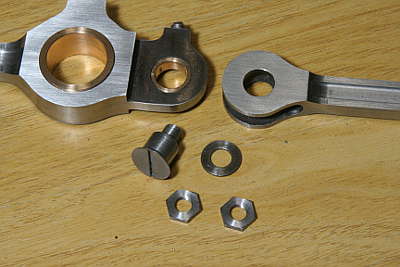
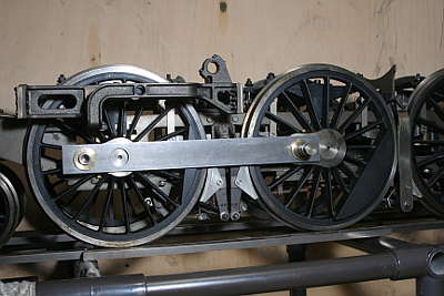
The knuckle joint fork and eye have 0.3 mm clearance, and the eye's bush hole is tapered at both sides. These are in order to let the front and rear side rods be able to bent at the joint according to the driving wheel's side play. The joint is fixed with a counter sunk bolt from back side and secured with thin double nuts at front.
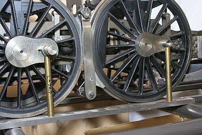
The side rods are completed. Note the first and third crank pins are closed by flanges. I already introduced the flanges in October 2008 article.
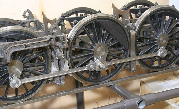
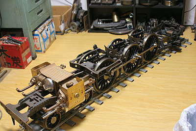
Rolling test is done on 7.5 meter radius S-curve tracks. There was no tight spot.