< Valve Gear 1 >
After the expansion link, I started making a number of other valve gear parts. The valve gear dimensions are determined according to the prototype, except steam port width. I decreased 'lead' and increased 'lap'. The port width is already fixed in making piston valve liners.

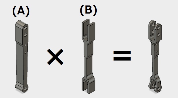
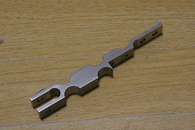
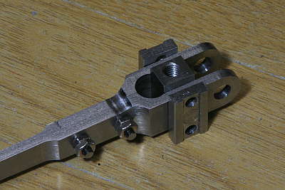
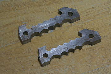
I started with combination levers. They have forks at both ends. The upper fork is separable so as to embed valve crosshead. From now on, I introduce finished photo first in order to make process easier to understand.
3D-CAD modeling makes it clear that the shapes of valve gear components are defined with two profiles from two directions. Actual cutting work also consists of two different cutting works from two directions. For convenience, I call (A) as width direction and (B) as depth direction. For the combination levers, I started from the depth direction.
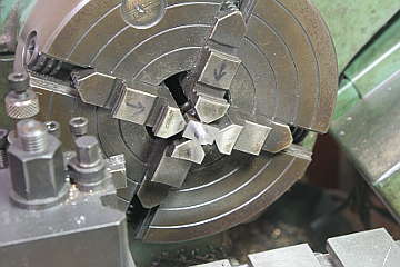
They are made from mild steel flat bars. Fillets are cut in advance, moving end mill vertically. It called vertical milling or plunge milling. The fork is first drilled at its bottom, then opened to a fork profile.
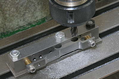
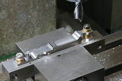
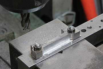
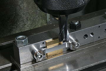
Cutting straight part between the fillets. Note a jig bolted down to the milling stage.
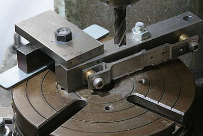
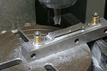
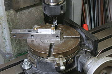
Cutting outer fillet of the fork shoulder in a rotary table. The same jig is utilized again.
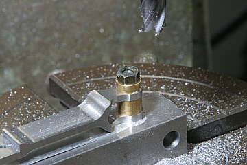
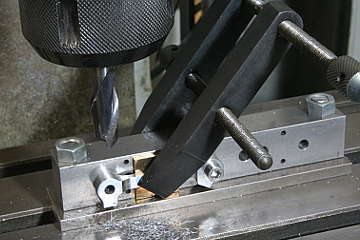
Now start cutting the width direction. At first, inner fillets of the heads are cut with vertical milling.
The round heads are finished in the rotary table. It is done for both the main body and the separated forks.
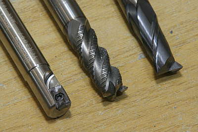
I utilized three kinds of end mills. From right to left, fine end mill, roughing end mill and carbide tipped end mill. I usually start with the roughing end mill and finish the last 0.1mm depth with the fine end mill. The tipped end mill is only for vertical milling. Because vertical milling causes quick wear of end mill tips.
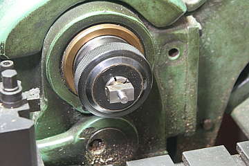
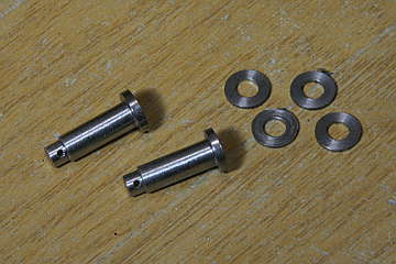
The combination lever and the piston valve rod are connected via valve crosshead. The valve crosshead is a block with right and left pins through the combination lever, and a center screw hole for valve stem. Both pins are turned in the lathe. A pin is turned in four-jaw, reversed and the opposite pin is turned concentric in the collet.
The valve crosshead is secured in the combination lever fork and covered with two sliding plates in both sides. The sliding plates will slide in the steam chest back cover.
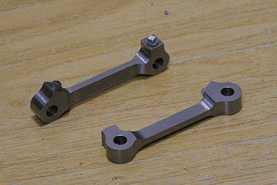
Next I made union links. They also need two directions cutting and they have oil caps at both ends.
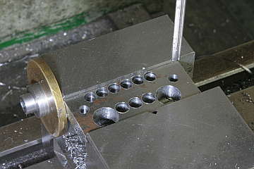
Using large plates as material, inner fillets are drilled and reamed instead of vertical milling. And I added drilling for easy sawing. The second photo shows sawed off parts.
This time I started with width direction cutting. I utilized the jig again. Middle thin part and round heads are cut.
Next is depth direction. The second photo shows cutting side face of the head.
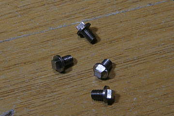
The oil caps are turned from round bar. They are screwed down into the union link head. The combination lever and the union link are connected with a pin, washer and split pin.
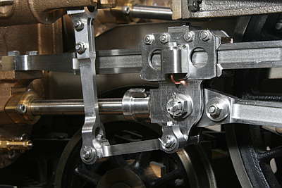
The combination lever, union link and crosshead are connected like this.