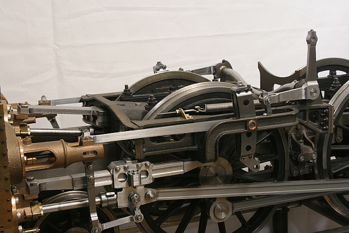
< Valve Gear 3 >
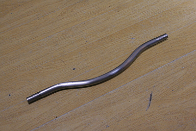
Both of lifting arms are synchronized through the weighshaft. The weighshaft is curved in order to clear the boiler. I made it from a steel round bar. It is not easy to bend but not impossible. I utilized 10 mm dia. round bar.
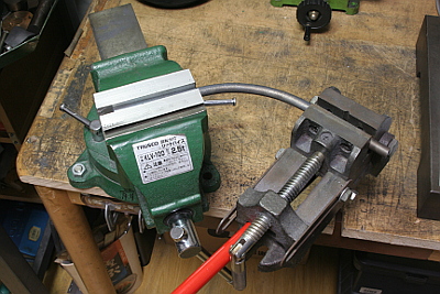
First the center gentle curve is bent. Before operation, the material is heated to bright red with a gas torch. Both straight parts are chucked with two vises and bend the center part between them with maximum radius.
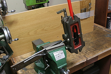
The sharp curves in both ends are bent with a jig. I added a grip handle to the vice so as to strengthen bending force. The both straight limits must be on the same line. I took the time to adjust it.
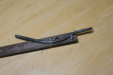
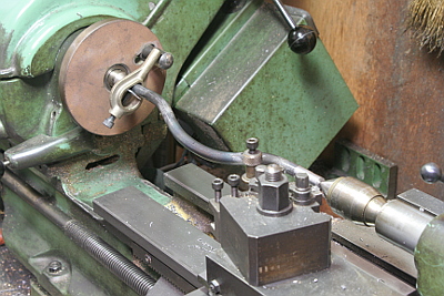
Cutting steps in both ends. Note the weighshaft is held between lathe head and tail stock centers. This operation makes the both straight limits precisely on the same line.
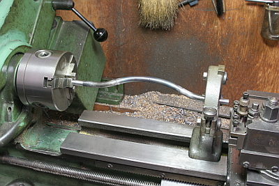
At last the both end faces are cut to final length with the fixed steady.
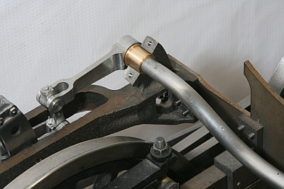
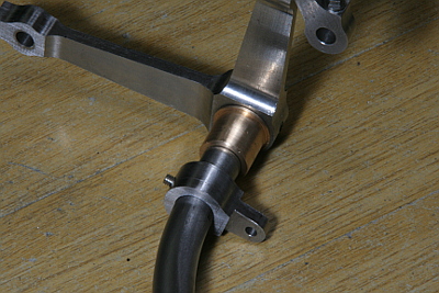
The weighshaft is held on the motion plate with gunmetal bushes. The lifting arms are set outside of the bushes. They are secured by set screws.
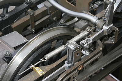
The radius rods are pulled up by coil springs against gravity. Specifically, the weighshaft has a crank that is pulled by a line of coil springs. The springs give rotation force to the weighshaft so as to pull up the radius rods. Spring force could be adjusted by the screw end of the front hook. It is adjusted so that the radius rods keep neutral without any external force.
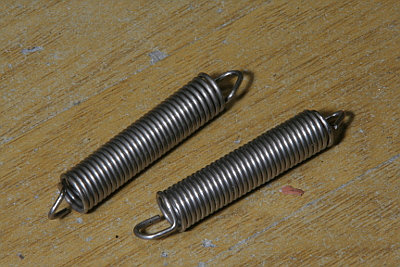
If we reduce the size of a full-scale coil spring due to the scale of a model, the coil spring becomes too strong for the model's weight. It is because the spring force is proportional to the squares of the scale, while the weight is proportional to the cubes of the scale. I reduced coil wire thickness from the scale size 1.6 mm to 1.2 mm, and increased coil winding number. They were coiled in the lathe.
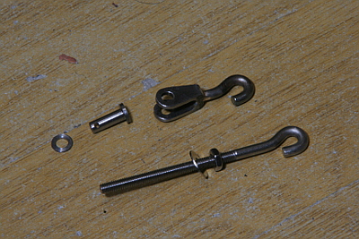
The photo shows parts around the coil springs. Both ends of the coils are pulled by hooks. One hook is adjusting screw and the other is connected to the crank.
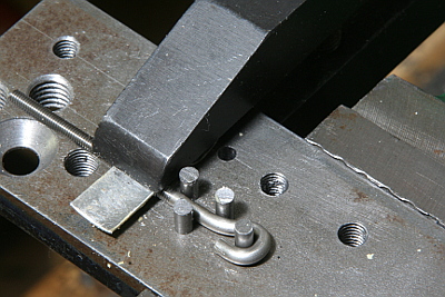
The photo shows a jig to bend the hooks. Due to bending steps, the pins are push into the plate one by one.
The crank is secured on the weighshaft by a set screw.
The valve gear parts after the expansion links are completed. The return cranks and the eccentric rods are remained.