< Gresley Valve Gear 1 >
Gresley conjugated valve gear is a device that drives inner valve by means of outer two valves' conjugated motion. In case of C53 loco, outer two valves are driven by Walschaerts valve gear and the inner valve is driven by Gresley valve gear.
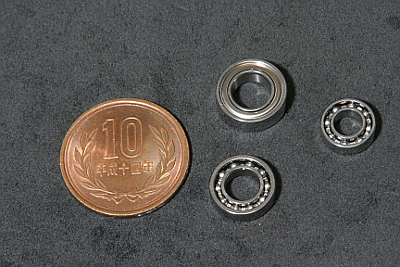
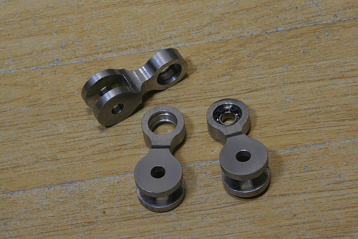
Full size C53's Gresley valve gear utilizes ball bearings. So I employed miniature ball bearings for my loco. Those are ten stainless steel ball bearings of three kinds, with or without side covers due to required thickness.
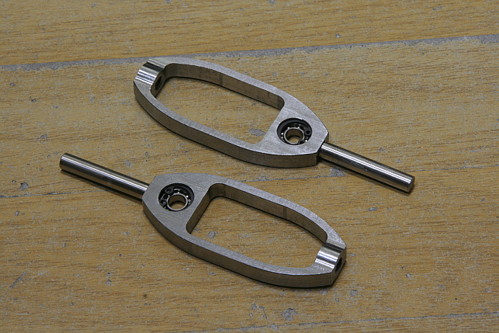
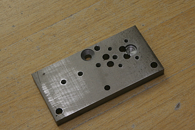
The photo shows parts called valve spindle guides located in front of the valve spindles and have windows in order to be connected to the short and long levers. Opposite end of the shaft has a thick bush part into which the valve spindle is screwed. So you need to cut and finish the thickness. There is a pocket for the bearing. I employed 10mm O.D. bearing. That is secured with a snap-ring, therefore the pocket has a groove for the snap-ring. Light press fit is ideal for ball bearings but difficult to finish the pocket that way. So I employ Loctite to fix the bearings. A care must be taken not to let liquid overflow into the bearings.
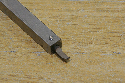
You need a special tool to cut grooves for snap-rings. I made it by carving an old boring tool with grinder, rotary tool and oil stone.
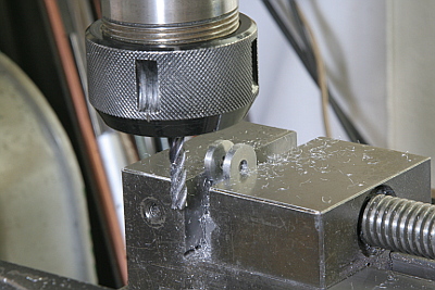
The parts are cut from steel flat bars. At first, the bearing pocket is opened in the lathe. The groove for snap-ring is also cut.
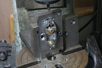
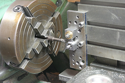
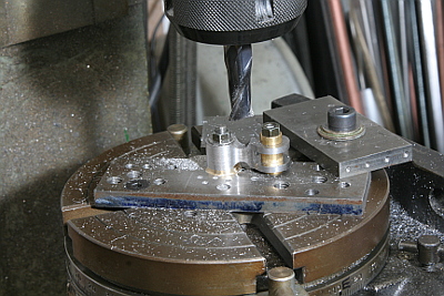
I prepared a jig to machine the parts in the rotary table. All of holes in the jig are necessary.
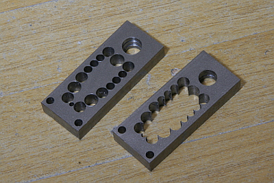
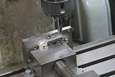
In order to open the window, drill a series of holes and saw off by a fret saw. Note two holes located opposite to the bearing pocket. These are only for fixing the part on the jig and will be finally sawed off.
The window is finished in the rotary table. The jig has center holes for locating the jig to the table center, fixing holes for parts and fixing holes for the jig itself.
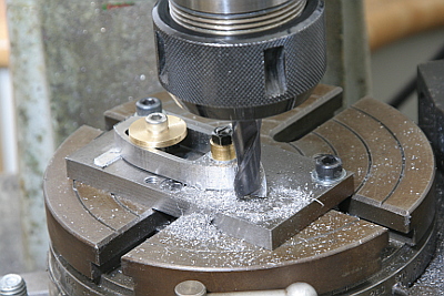
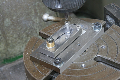
Saw off excess area and finish outer shape in the jig. Two positioning pins against two corners of the window are hiden under the brass disc. You can find them in the next photo.
The thickness profile is started with cutting radius of the bush. At this time the top of the bush is still lower than total thickness.
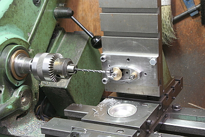
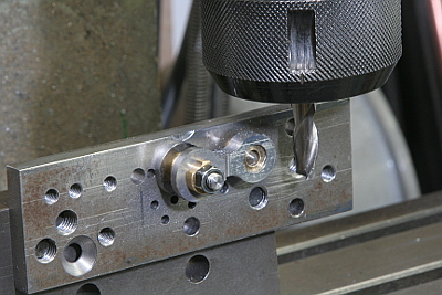
Open screw holes at the both ends of the part. I utilized the lathe instead of the miller in order to align both holes precisely.
Finally mill off remained area around the bush to desired thickness.
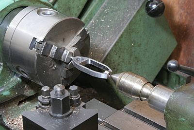
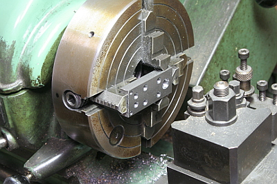
After finishing the body, prepare a front shaft from a round bar and screwed and glued into the body. Then chuck in three-jaw and check that the shaft does not tilt.
Next I made parts called valve spindle link that is connected between the valve spindle guides and the short and long levers. The purpose of the indirect connection is to eliminate side shift of the axis due to the levers' roll.
The parts are similar to Walschaerts valve gear parts and can be machined with the same manner. The photo shows cutting an inner radius shape of the thickness profile.
Finish the fork end by end mill. Note the part is held vertically in a vise because the fork bottom is square.
Finish the both heads in the rotary table.
Finally finish the thickness step profile.