< Gresley Valve Gear 3 >
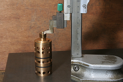
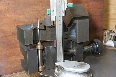
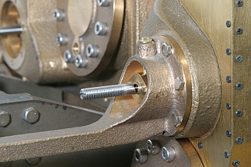
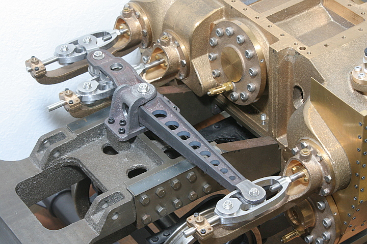
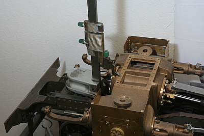 There are so many components mounting between the large lever bracket and
the valve spindle, i.e. front buffer casting, main frames, middle stretcher,
and the cylinder block. It is cause of error accumulation. The photo shows
measuring height of the cylinder block directly from the bracket bolt down
face. Also x and y axis distances are measured with calipers. The bracket
height and positon will be determined from these measurements, not from
the design.
There are so many components mounting between the large lever bracket and
the valve spindle, i.e. front buffer casting, main frames, middle stretcher,
and the cylinder block. It is cause of error accumulation. The photo shows
measuring height of the cylinder block directly from the bracket bolt down
face. Also x and y axis distances are measured with calipers. The bracket
height and positon will be determined from these measurements, not from
the design.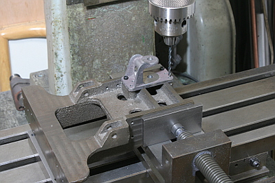
Clamp the bracket on the front buffer casting. Then dismantle the front buffer casting and drill & tap screw holes for the bracket.
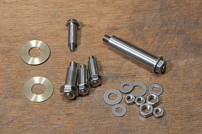
They are pins for connecting the Gresley valve gear links. They are made from free-cutting stainless steel rods. Both ends of each pin are threaded and closed with nuts.
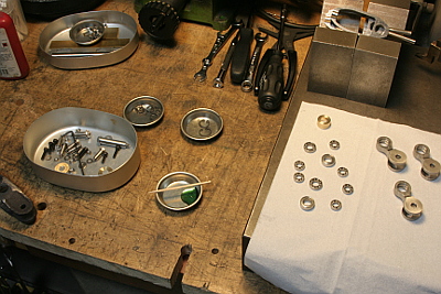
Each ball bearing should be light press fit into the recess, but it is not easy to finish the recess diameter so. In order to make life easier, I glued each bearing into the recess with Loctite. Care must be taken not to let the glue into the bearing.
The valve setting will be done with the steam chest gland as a reference. So the distance from the gland and the steam port is measured here.
Calculate front and back 'valve open' positons from the measurement and mark them on the valve spindle.
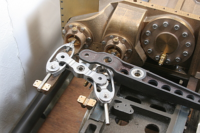
The parts of the Gresley valve gear are much complicated like 'cast puzzle' and you can't assemble them step by step. They should be gathered to each final position at a time and finally secured by all pins.
Here I found that the large lever body clashes with the arm of inner steam chest front cover. So I filed off each part until they clear with each other.
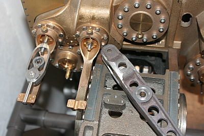
The valve setting is done as follows, with the mark on the valve spindle (Left side photo).
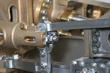
1. Starting with two outer valves. The reverser is set to forward position. At front and back dead centers of the crank pin, check each opening length (lead). Then adjust the valve crosshead position so as to let the front and back lead values equal. Specifically, as threaded part of the valve spindle back end is screwed into the valve crosshead, adjust screwed distance and secure with a lock nut (Right side photo). After that, set the reverser to backward position and do the same adjustment. The two results should be the same. If there is difference, choose average of them or give a little priority to forward position. It is typical adjustment of Walschearts valve gear.
2. Assemble whole set of Gresley valve gear. Only the inner valve spindle is temporary screwed into the valve spindle guide in front of the valve spindle. The other parts are finally fixed to the designed position with lock nuts.
3. Inner valve position is adjusted with the same manner as '1'. That is to say, at front and back dead center of the inner crank shaft, make front and back lead length equal. This case, the adjustment is done by screwing the valve spindle into the valve spindle guide and fix with a lock nut.
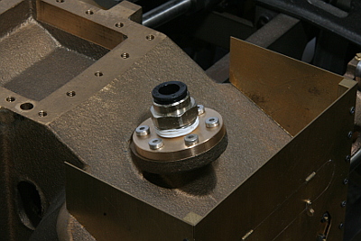
Now is the time for the air testing. I made flanges that have tube connects for air compressor and bolted down to left and right steam inlets of the cylinder block. Also I inserted suitable packings between six of driving wheel axle boxes and horn stays, in order to maintain each axle in normal height.
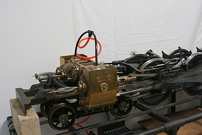
Fix the reverser in forward position and supply compressed air to the cylinder. Less than 0.1MPa the wheels start spinning. As it is three cylinder, six blasts are heard in one rotation. The six voices' timing should be uniform. I checked forward, backward and very slow running. I was uneasy in the test for its new and complicated cylinder design, so it is delightful success for me.
Video clip of the air testing --->
Now I had used up my C53 design. I have to start from designing the next component, so I need a break in the next month.