< Tender Axleboxes >
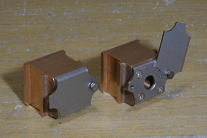
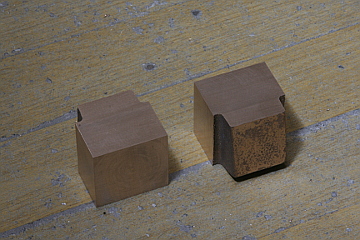
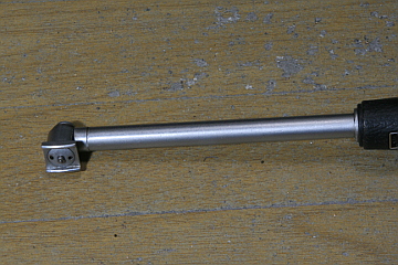
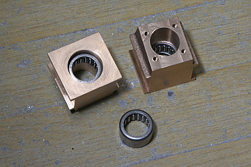
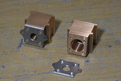
The next items are axleboxes. The photo shows finished goods. The body is cut from a gunmetal casting. A roller bearing is press fitted from the back side. There is a cover in front and the body has 'ears' to bolt down the cover, but it was difficult to form the ears in the casting. So I prepared a laser cut plate with the ears and screwed down to the casting. The cover is fixed to the plate with a bolt and can rotate around the bolt. The cover's upper edge is flanged in order to stop rotation at the horizontal position.
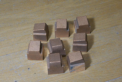
The casting consists of four axleboxes in one body. First I separated them with a hacksaw.
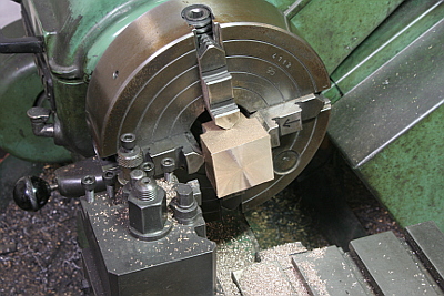
Finish the bottom face in four-jaw. I utilized the lathe because plenty of metal had to be removed here.
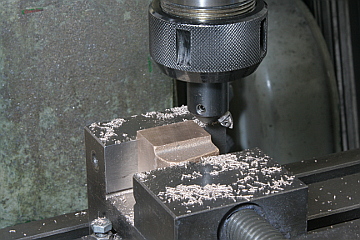
Each side face are set square to the bottom face and adjacent side face by the vise jaw and a square, then finished by a fly cutter. Five faces except the front tilt face were finished.
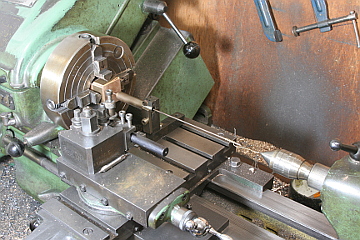
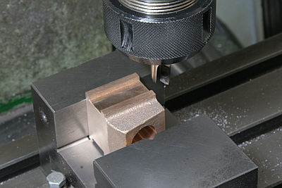
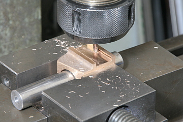
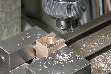
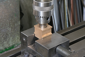
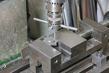
Bore of the axlebox is opened in the lathe. Scribe and punch the center and align center with the wobbler. Drill through and turn stepped hole with a boring tool. Note the axlebox is protected with two foiled brass sheets to prevent damage from the jaws.
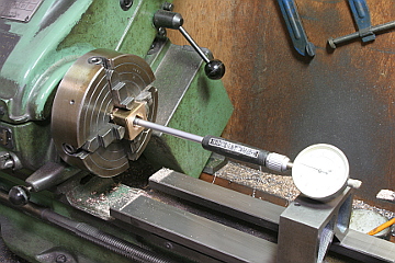
Here I utilized a bore gauge to finish the bore for press fitting of the roller bearing. O.D. of the roller bearing is 21.04 mm and I finished the bore I.D. 21.01 to 21.02 mm.
Cut slits in both sides by end mill. First the axlebox is chucked in the vise and a rough cutting is done remaining 0.2 mm as finish allowance.
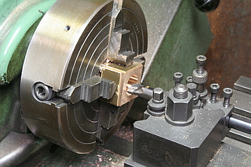
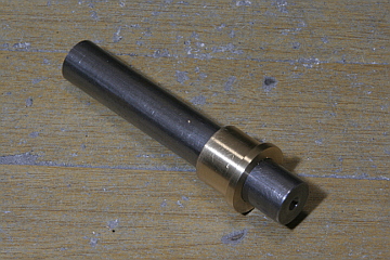
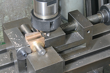
The final 0.2 mm is cut exactly the same distance from the bore center. The left side photo shows a brass bush in a round bar that is tight-fit to the bore. The right photo shows set up for cutting. Height of the tool is fixed during the operation.
The slit is cut in a bell bottom shape toward top and bottom. Tilt the vise in desired angle and do additional cutting with a thin end mill.
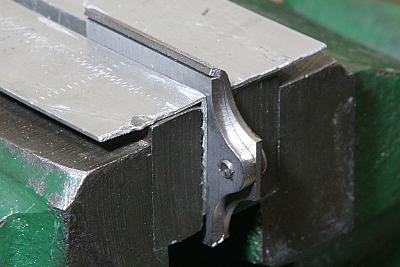
The tilt front face is finished by a fly cutter. The right side photo shows an angle gauge made from a scrap steel bar.
Here the roller bearings are press-fit into the axleboxes. I utilized sliding head of the milling machine. Insert the job between the vise jaws and press through a round bar. Incidentally, smaller diameter of the stepped hole should be larger than the bearing I.D. Otherwise you won't be able to push out a broken bearing from the opposite side.
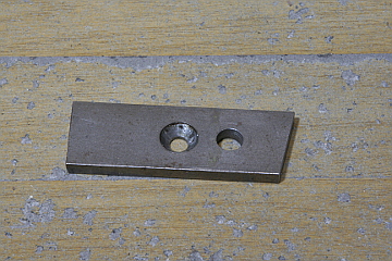
The front plate is 2.3 mm laser cut steel plate. Each hole is drilled and screwed or counter sunk according to the milling machine's X-Y stage control. The upper and lower edge of the plate is filleted by an R cutter.
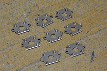
The cover is 1.2 mm laser cut steel plate and bolted down to the front plate. The top edge of the cover is flanged using the front plate as a former. Chuck the pair tightly in a vise and hammer through a suitable steel bar. Each pair of a front plate and a cover are marked here.
The front plate is fixed on the axlebox with countersunk screws. The screwed holes of the axlebox are also positioned with X-Y stage control. It is enough precise not to copy from job.
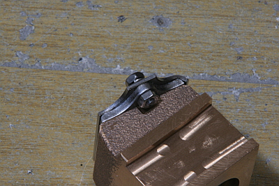
Full size axlebox cover is push against the axlebox by a coil spring. My model substitute a spring washer for the coil spring. The bolt is screwed through the front plate and secured with a lock nut.
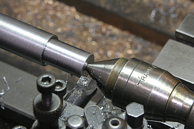
Here I finished the axles to ensure close fitting to the roller bearings in the axleboxes.
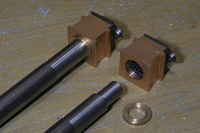
I inserted brass rings between the axles and axleboxes. The rings are push against the axlebox back faces. They adjust play of the axles and also prevent the axle steps from hitting the bearing cases directly.