< Tender Bogie Frames >
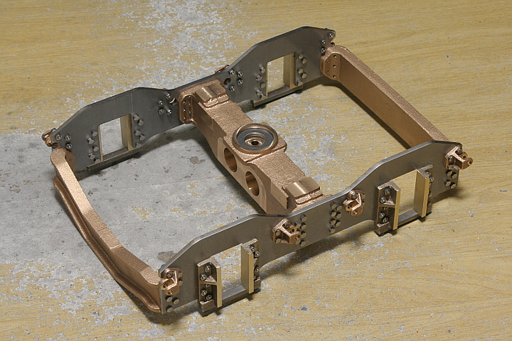
The main frames are connected with a bolster at center and two cross stays at both ends. The bolster and cross stays are cut from gunmetal castings. The bolster holds a thrust bearing at its center top. Two cross stays have different shapes each other. Only the cross stay under the coupler is bent so as to dodge the coupler.
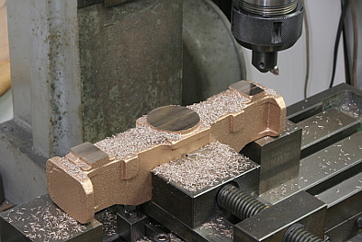
Let's start with the bolster. Three top faces at center and both ends are cut in the same height with a fly cutter. The face becomes reference plane of vertical direction.
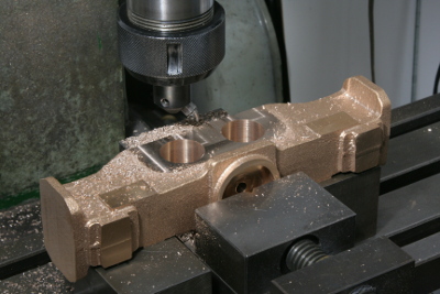
Finish four rectangle pedestals at front and back face of the bolster. The pedestals are for holding brake hunger brackets. They are cut by end mill. They become reference plane of longitudinal direction.
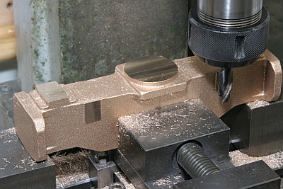
The bolster is reversed and clamped on the milling machine stage parallel to the x-axis. Then the screw down flanges at both ends are finished with an end mill. It requires maximum size end mill (20 mm dia.) that the machine can handle.
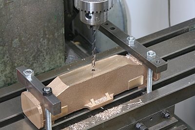
In the same setting, clean bottom face with a fly cutter and drill center hole (5 mm). The hole will be expanded to 12 mm finally.
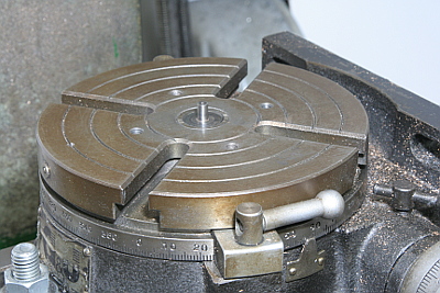
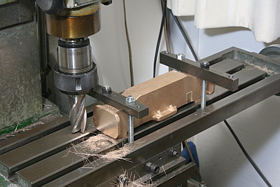
Fix the rotary table on the milling machine stage and insert 5 mm dia. arbor for centering of the bolster with 5 mm center hole.
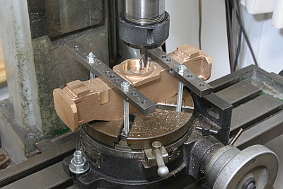
Drill through the center hole and dig round cavity for the thrust bearing with end mill. Lathe is more suitable for such kind of work but the bolster is too long to turn in Super 7 lathe.
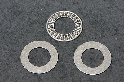
The thrust bearing consists of a roller bearing disc between two washers. Each washer contacts to each axle end and rotate with the bearing rollers.
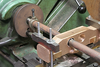
Bore 25 mm dia. holes for axle driven pumps. Cramp the bolster on the lathe table aligning the center. Start with drill to 16 mm. Expand the hole to 24.7 mm by a boring bar chucked in four-jaw. Then finish to 25 mm with a tool in a round bar held between centers.
The axle driven pumps have flanges screwed down to the bolster. Then I finished the bolster's screw down face precisely vertical to the bores. It was done with a fly cutter. Now all of cutting process for the bolster are finished.
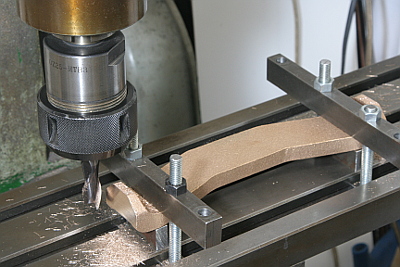
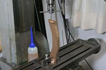
Next is the cross stays. They require only finish of screw down flanges at both ends. They are cut by end mill. Incidentally, final length of the bolster and cross stays is 206 mm.
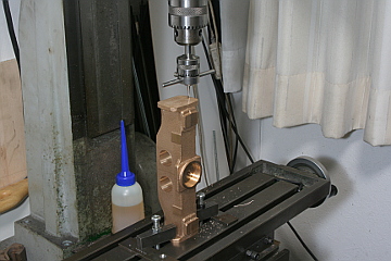
Although it needs a lot of screws to fix the bolster and the cross stays between the frames, at first, drill and tap one screw hole in each flange. Erect the job on the milling machine stage and cramp the bottom flange. The milling head is raised up to the upper limit.
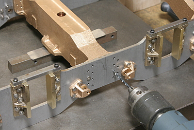
Temporary assemble the frames on the surface plate aligning the bolster and cross stays vertically, pour instant adhesive to lock the assemble. Then drill 3 mm countersink on the bolster or cross stays through the 3 mm holes in the main frames.
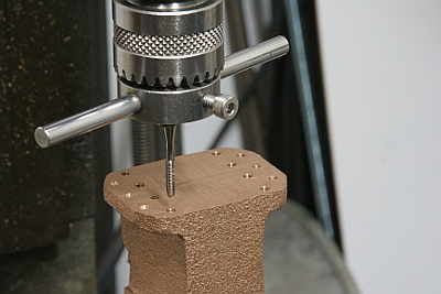
Disassemble, return to the milling machine and drill 2.5 mm holes through the countersinks and tap M3 screw holes.
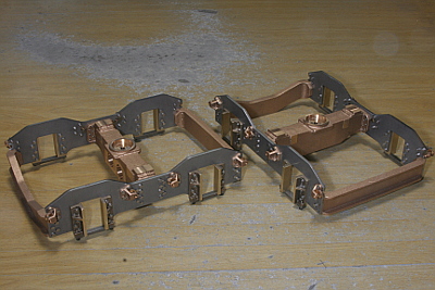
The bolster will be drilled and tapped to fix many other parts. So they are fixed temporary between the frames. On the other hand, the cross stays are fixed permanently with Loctite. I planned to paint whole job after assembly.