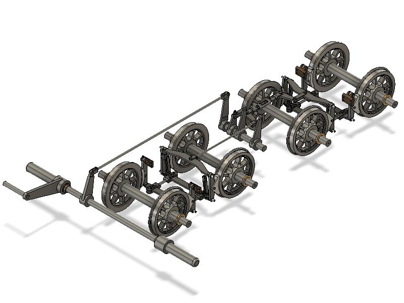
< Tender Brake System 1 >
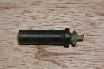
The tender is equipped with a foot operated brake system. Full scale tender has two air cylinders at the center of the chassis but my model has a link from here to a foot pedal at the front of the chassis. Other links from the bogies are the same as the full scale.
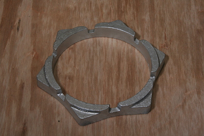
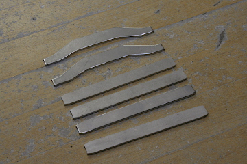
Brake shoes for the tender are also made from cast aluminum. The wheel diameter is comparatively small, so I arranged six shoes in a casting with the same diameter as the wheel.
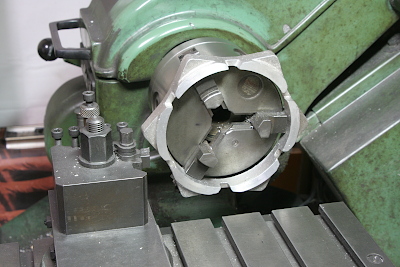
Finish the top and bottom faces parallel in the lathe. Note the work is held by three jaws' outer edges.

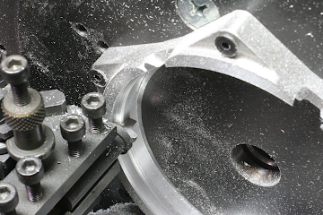
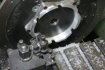
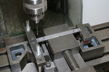
A large face plate is used for farther operation in the lathe. The face plate is mounted on the rotary table and screw holes for each shoes are opened. The rotary table is used in order to decide the hole positions with 'polar coordinates'. Plane holes in the casting are also opened here. Scribe and open two holes in advance, mount to the face plate on the rotary table, then drill rest of holes.
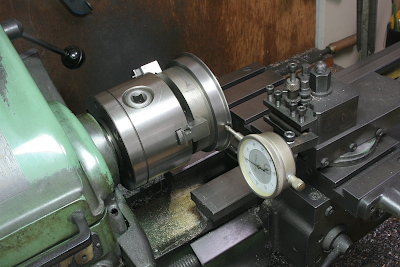
Before cutting tread faces of the shoes, the lathe top slider's angle is set to the wheel tread angle, as the photo shows, using a dial gauge.
The section profile of the brake shoes is a negative copy of the section profile of the wheels. The profile is the same as the driving wheels. Therefore I utilized the home made cutter for the driving wheel brake shoes again.
Finish the tread face with the taper cutting, utilizing the adjusted top slider angle.
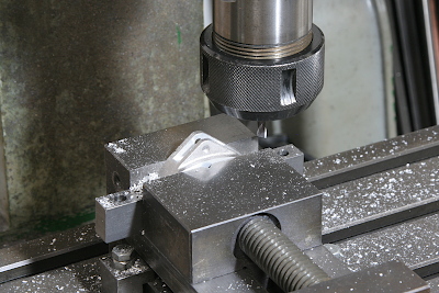
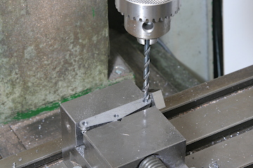
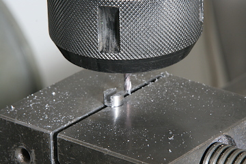
Cut a slot for holding the brake hanger with an end mill.
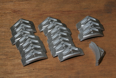
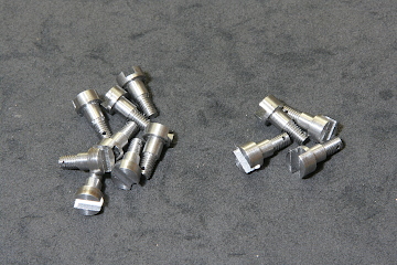
The tender brake will be utilized as a main braking system of the loco, so I prepared double number of shoes as spare parts.
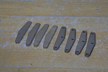
The brake hangers are laser cut parts with drilled holes.
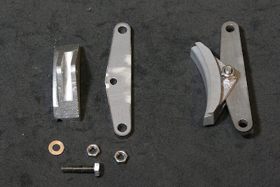
Assemble the brake shoes and the hanger. I use a bolt and a nut, tighten them properly and lock them with additional nut, so that the shoes can barely rotate with a braking force and keep adequate angle after releasing.
The brake beam is made of a laser cut plate with shafts at both ends. It's the same structure as the engine's brake beams. The laser cut plate is drilled in the vise.
The both shafts are made of silver steel rod. Turned steps in the lathe, cut a slit by end mill, cut thread with a die, and drill a cross hole for a split pin. The cross hole should be opened before cutting thread.
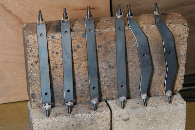
Silver solder the shafts at both ends of the laser cut plate.
(to be continued)
My article of the C53 cylinder block construction was published in Model Engineer Magazine issue 4610. As a new information, I attached dimensional drawings of the cast patterns.
Click ->