< Tender Brake System 2 >
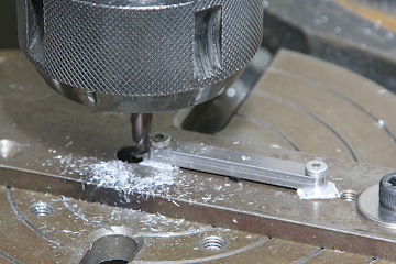
Some of brake beams have brackets for links. The brackets is bent from a steel band plate. The round bush part is cut in the rotary table. Note a square bar pushes against the bracket and prevents the bracket rotating during cutting.
Two of six brake beams have the brackets. The same brackets are mounted on the bolsters and both brackets are connected by the links.
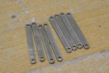
The links are a pair of band plates with holes at both ends. The round ends are cut in the rotary table.
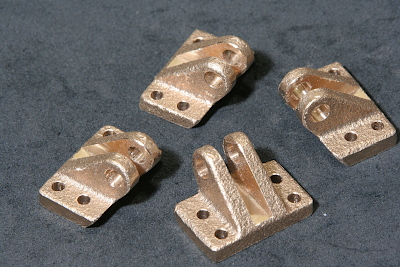
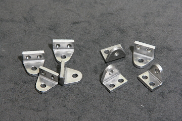
Some of brake hangers are connected to the bolster at their top with brake hanger brackets. The brackets are made from cast gunmetal as follows.
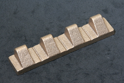
I prepared a wood pattern and ask a local foundry to prepare the integrated cast gunmetal.
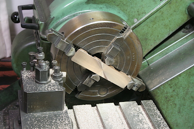
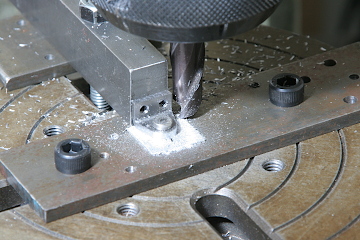
Finish back face in four-jaw.
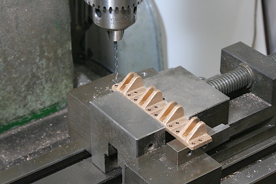
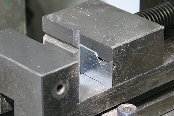
Chuck in the vise and cut slits by end mill and drill holes.
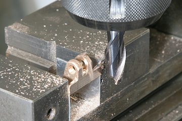
Separate each bracket by fret saw and drill and ream a hole for a cross pin.
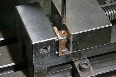
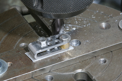
The brackets have undercuts that could not form in single side casting. Then I cut them here. Note an angle gauge of aluminum plate is pasted on the vise jaw with double sided tape.
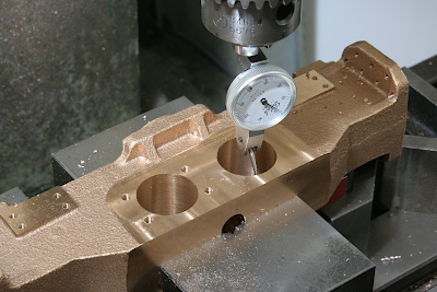
As the last cutting operation for the bolsters, open screw holes to mount the axle driven pumps. Note the center of the hole is aligned to the milling head center with a dial gauge. Then each hole position is controlled by X and Y axis of the table.
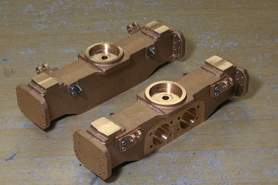
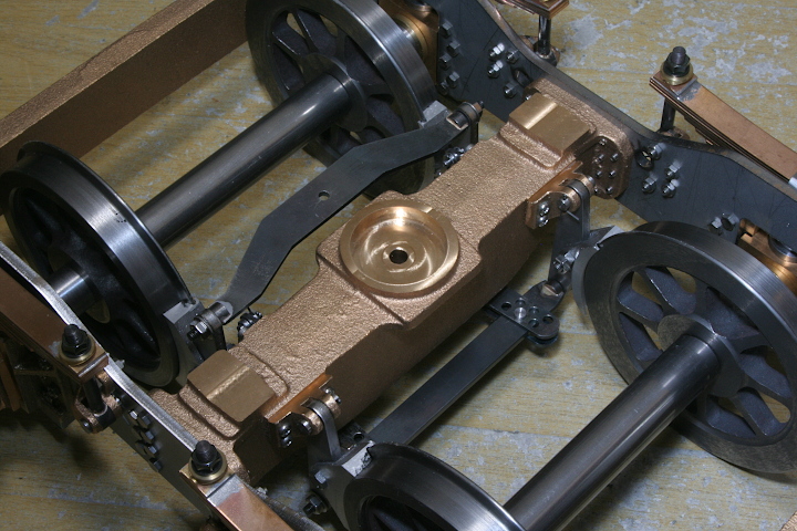
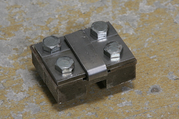
The link brackets and brake hanger brackets are mounted to the bolsters.
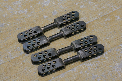
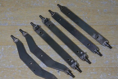
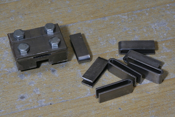
Two of bottom brake beam is connected with the brake beam links (photo). They are made as follows.
The fork plates at both ends are bent from steel band plates. I did it with the usual bending jig. Thickness of the middle plate of the jig can be adjusted due to desired gap of the fork.
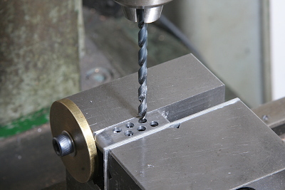
Open zigzag holes in the forks to follow prototype.
Cut the ends round on the rotary table. Note the zigzag holes are utilized to screw down the fork onto the table. After that, silver solder two forks on a round bar.
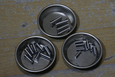
Here I made necessary pins for the brake assembly. All of them are turned from a silver steel round bar and drilled cross holes for split pins.
The brake system of the bogie is completed. Unfortunately, the components are almost invisible from outside.