< Axle Driven Pump Body 2 >
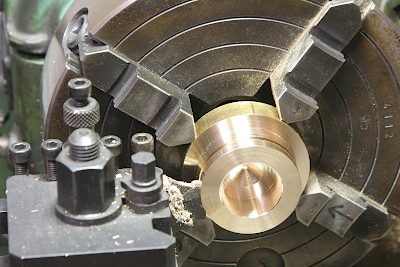
Next I prepared flanges to fix the pumps to the bogie bolster. They are made from 40 mm dia. brass rod. After boring the center hole, part off in desired thickness.
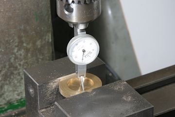
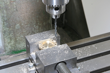
The holes around the flange should be arranged concentric to the circle hole. After aligning the head center to the circle hole center with DTI, holes around the flange is determined by X and Y axis of the stage.
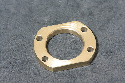
Finished flanges. Top and bottom chords are cut in order to fit the flange to the bolster face.
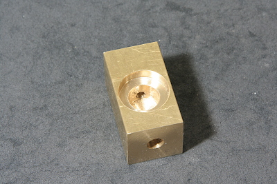
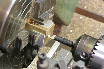
The valve body is made from a 25 mm brass rectangle bar.
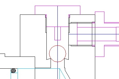
We have to form a valve seat in the upper delivery section of the body. Angle of the seat edge is 75 degrees.
The valve seat is first drilled a step, then cut the edge with a home made tool. The photo shows the tool called D-bit. After that 'seating' is done as I introduced last month.
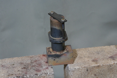
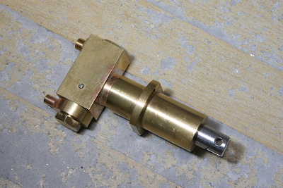
Finally whole components are assembled by silver soldering. First, the flange is soldered to the bore, next the bore is soldered to the body. Note the flange is pulled up to prevent falling down during the soldering operation.
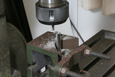
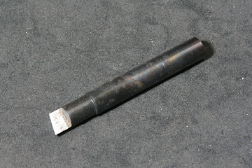
The pump ram is made of free-cutting stainless steel bar. A slit for the strap is cut at the rear end. The ram is held in vee block and cut the slit by an endmill.
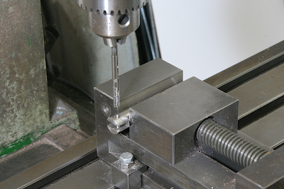
Drill and ream a hole for the pin to connect to the strap.
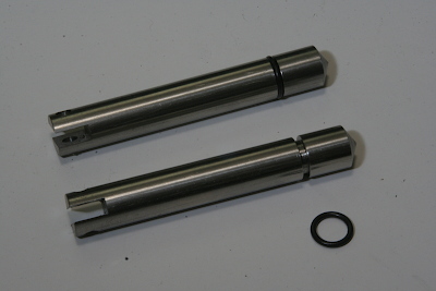
Cut a groove for o-ring, then the ram is completed.
Finally the pump is assembled with stainless ball valves inside. All of plugs were sealed with Loctite #510. Note a small screw at a side face of the body, that is to set a limit to the ball valve stroke.