< Tender Brake System 3 >

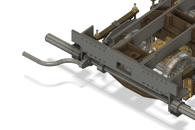
Next, equip the chassis with the foot brake system. Incidentally, I had designed the right foot step rotating with the brake pedal, but I modified it fixing so as to stable driver's foot.
Starting from four arms on front and middle braking axles. Each arm is made from a steel bush and silver soldered arm plate. The bushes will be mounted on the axles with set screws. The photo shows laser cut arm plates of 3.2 mm thickness. The left two arms will be utilized. The right two arms are for air cylinders of prototype which I have no plan to use.
Two arm plates for front brake axle were recently designed and have no time to ask laser cutting. So I cut them from steel bars in the rotary table.
The bushes are turned from steel round bar. Cut slits for arm plates by end mill and open screw holes for set screws. There are various diameter and thickness.
The bushes and the arm plates are silver soldered.
The two arms for middle brake axle is mount on the axle and held in the chassis. Note two small recesses for the set screws drilled on the side of the axle.
The brake pedal is bent from 10 mm dia. stainless steel round bar. Anneal the bar to dull red by propane gas torch and bend it with bench vise and a jig. For the first L-shape bending, calculate length of the center line of the arc part, hold remaining two straight parts in both ends straight by two vises, bend the material freely to desired angle. Then you can get desired radius.
For the second crank bending, I prepared a jig as the photo shows. The jig is for keeping first bending part in shape. The other end is held by a vise as same as the first bending.
Cut and clean both ends in desired length and silver solder to the arm. In order to let solder flow freely, cut four grooves in the hole by a fine triangle file. After that, just in case, drill and ream 3 mm taper hole and drive a taper pin. Finally the stainless steel part is polished by fine emery cloth. The rest steel parts will be painted.