< Tender Brake System 4 >
Here I prepared components around the steps. The drawings show section around the step. A brake bearing (black) which holds a brake axle (cyan) is put into a steel angle plate column and secured by a nut. Then the step (magenta) is screwed into the brake bearing.
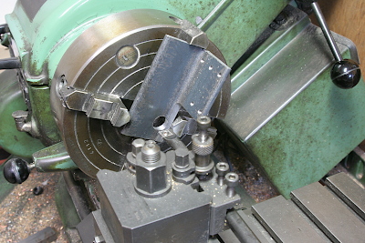
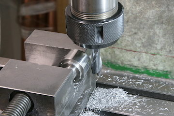
Remove the steel angle plate columns from the chassis and open holes for the bearings. The column is chucked in four-jaw and bored by a boring tool. The bearing thread is M14 x 1 so the hole is 14 mm dia.
The steps and the bearings will be rubbed by feet. Therefor I made them by stainless steel without paint. First the brake bearings are turned from 30 mm dia. stainless steel round bar. In order to tighten by a wrench, two opposite faces are cut by end mill.
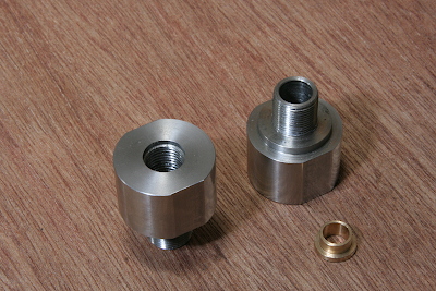
The brake axle is held by a gunmetal bush in the brake bearing. The bush will be glued into the bearing with Loctite. It will be done after the whole components are assembled and centered.
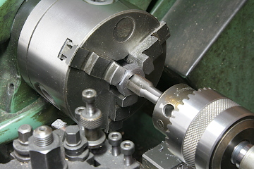
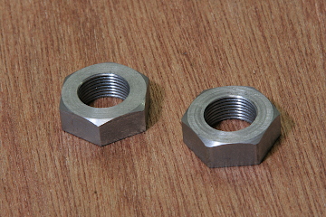
The M14 x 1 nut is made from a 25 mm dia. silver steel round bar. First the bar is turned to a disc with desired thickness in the lathe. Then the disc is cut to hexagonal shape in the rotary table, that is 22 mm flat to flat distance.
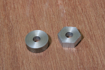
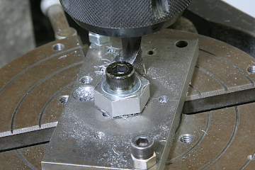
Return to the lathe and open M14 x 1 screw hole.
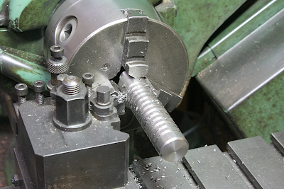
The steps are made from 20 mm dia. stainless steel round bar. They are cleated with a series of shallow grooves cut by a parting tool.
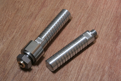
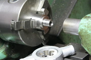
Cut a step in an end and cut threads of M12 x 1.25 with a dies. Then two opposite faces for wrench are cut. The left one in the photo shows the step screwed into the brake bearing.
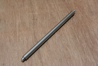
The brake axle is 13 mm dia. round bar with 8 mm dia. steps at both ends. It is also made by stainless steel.
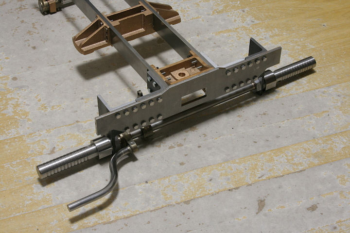
The assembled components. The brake pedal and the arm are parts made in the last month and fixed onto the axle with set screws. There is no recess for the set screws in the axle yet. They will be cut after the final adjustment.