< Water Gauge >
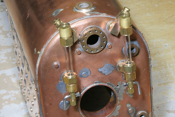
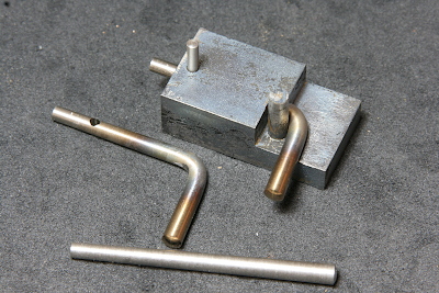
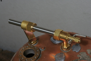
Here I started boiler fittings. The first item is the water gauge on the backhead. First, I introduce a completion photo.
Same as the prototype, I prepared two water gauges in both sides. In order to make the water gauge indicate up to the round top water level, I elevated the upper body with a rectangle bar. In order to prevent air lock in the upper body, bypass lines will be connected from the rectangle bar top to the steam turret. The parts on top of the rectangle bars are the connecting parts for the bypass line. Under the lower bodies, there are drain valves made from stainless steel taper pins.
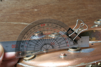
Due to many times' repairs of the boiler, the backhead is distorted and the bushes are badly tilt. I don't try to correct them but make the water gauge to fit the error. The bush angle is measured with a protractor and a rule.
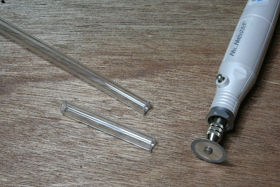
I employed 9 mm dia. thick glass pipe for the gauges. It is cut by a diamond disc tool.
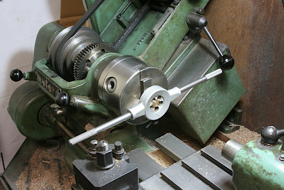
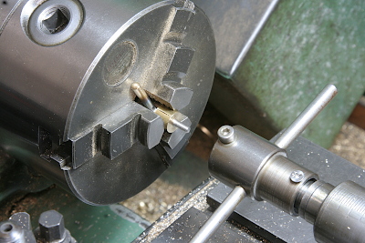
Screw for the cap nut is cut by a die. The screw size is M14. I utilized cheep throw-away tap and die set. They are enough useful for threading brass rods. The chuck and the die handle are alternately rotated by hand.
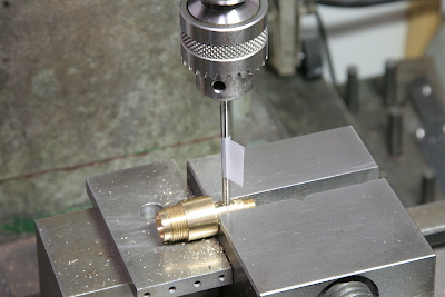
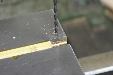
On the lower body, drill and taper-ream a cross hole for the drain valve made by a taper pin. Note a white tape indicates desired depth of the taper reamer.
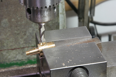
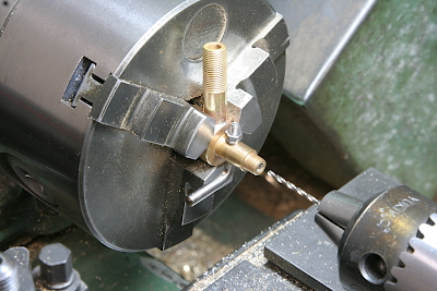
Dig a cross hole for the nipple. Note the body is clamped in a desired angle to fit the tilt of the bush.
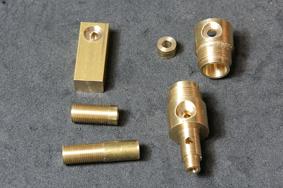
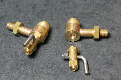
The parts of the water gauge, ready for the silver soldering. The small ring is a connector between the upper body and the rectangle bar.
In order to bend the taper pin without distortion of the taper tip. I prepared a jig as the photo shows.
Chuck the tip of the bent pin in a handmaid brass collet, turn a step and cut threads by a die.
Chuck the lower body in three-jaw, insert the valve cock and drill cross hole in the valve.
The valve cock is secured in the lower body with a spring washer and two nuts.
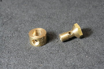
The photo shows connecting parts for the bypass line from the rectangle bar top. A copper tube will be silver soldered into the side hole of the tablet. The hollow plug has a cross hole. Steam from the hollow plug comes into the tablet and is sent out through the copper tube. The hollow plug is turned in the lathe, drilled the cross hole and parted off.
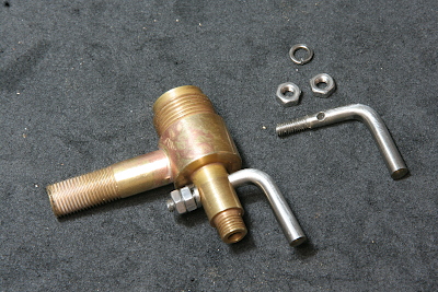
So far, the first photo had been the completion. But it was found that the valve cock will be clashed with the firehole door handle. It will be cleared if the valve cocks are sideways instead of frontways. So I divided the lower body into two parts in order to change the cock direction. The valve part is fixed with a lock nut.
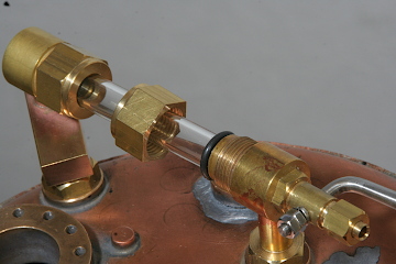
The upper and lower body are aligned with a round bar of the glass pipe size. The glass pipe is sealed with O-rings squeezed by the cap nuts. The nuts should be tightened only with your fingers.
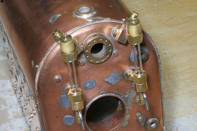
The final completion of the water gauges. Note the direction of the valve cocks are different from the first photo.