< Steam Turret and Valves >
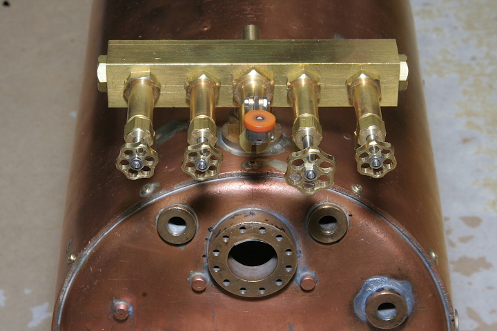
The steam turret equipped with valves will be mounted on the top of the backhead. Followings are the making procedures of them.
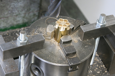
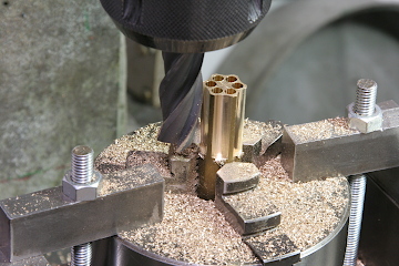
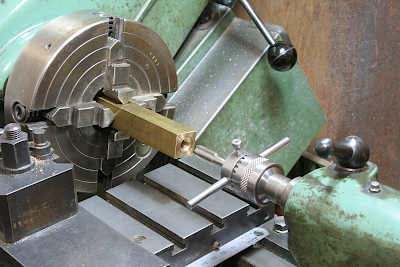
The blower and other valve handles have complicated shapes. Some suppliers provide lost-wax handles. Here I made the handles from brass round bars. Start in the lathe with a turning round profile. Mount the three-jaw with the job on the milling table, drill and mill hexagonal handle shape.
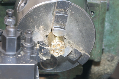
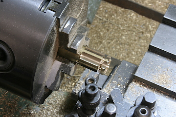
Return to the lathe, finish the outer profile, and part off.
This is the method to get many handles at a time. Part off one by one.
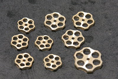
I prepared three sizes of handles. Finally, I didn't use the largest one.
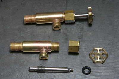
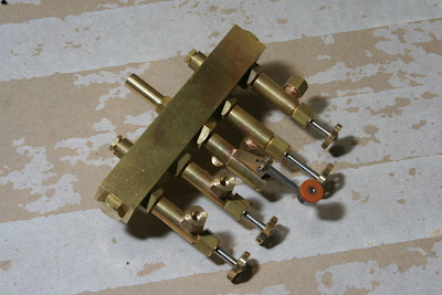
The photo shows valve parts and an assembled valve. The valve body is a needle valve and is sealed with an o-ring.
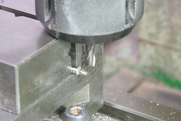
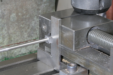
The needle valve end is cut square by an end mill in order to fix the handle. Note the needle is rotated every 90 degrees with a square collar and a square gauge.
The center hole of the handle is finished square with a fine square file.
I prepared four valves. One is for the blower with a large handle. The other three are for an injector, a generator, and a donkey pump with small handles. The body size is the same.
The turret is made from a brass square bar. Drill through the steam passage and tap both ends for plugs.
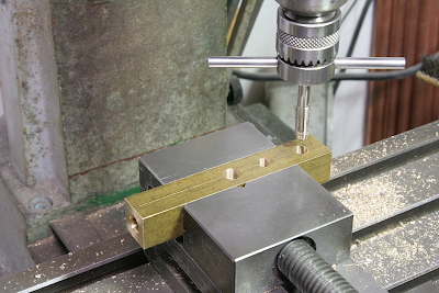
Drill and tap holes for the valves.
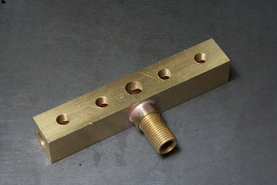
Silver Solder a fat stud to screw into the boiler.
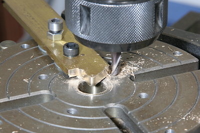
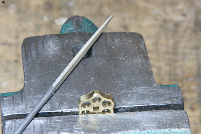
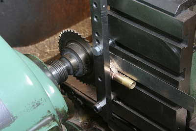
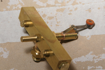
The last one is the whistle valve. A lever bracket is made from a brass flat bar. The photo shows cutting a radius in the rotary table.
The lever bracket is silver soldered onto the valve body. After that, a slit is cut in both the bracket and the body by a slitting saw.
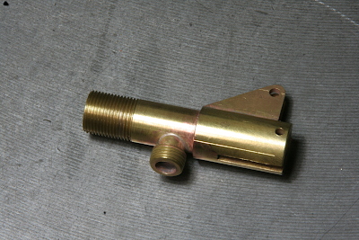
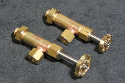
Silver solder a nipple for connecting the outlet tube. Then the body is completed.
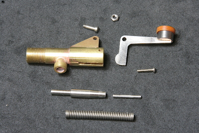
These are all of parts for the whistle valve. The valve shaft is inserted from the left and pushed against the valve seat by the coil spring. The lever pushes the small pin and opens the valve.
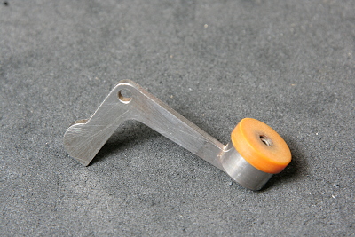
The lever consists of stainless steel body and a heat-resisting plastic button.
There is no space for the coil spring in the valve body. Therefore I prepared a cylindrical pocket for the coil spring on the other side of the valve body. Incidentally, the connecting parts on both sides of the pocket are for the bent lines from the water gauge top bodies.
There is not a pressure gauge yet. It will be mounted after designing the total cab layout because its visibility is important.