< Lubricator 1 >
The full-size lubricators of the class C53 are set on the left and right running boards and are driven by arms from the expansion links. The model lubricators could be made within the scaled size of the prototype. They could also be driven by the expansion links.
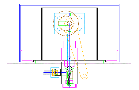 The drawings show the section of the lubricator. The blue rectangle around
the lubricator shows the scaled lubricator case. The inner box is the oil
reservoir of the lubricator. This time, for the test driving, I prepared
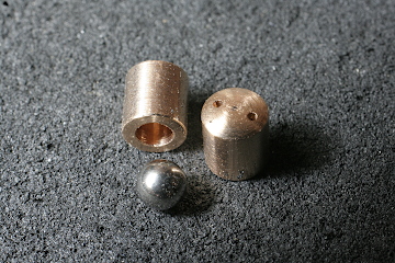
only the inner lubricators. They are Wakefield type, which is the same
as William's but driven by a one-way clutch instead of the ratchet feed.
The valve ball is pushed up to the valve seat by a coil spring.
The drawings show the section of the lubricator. The blue rectangle around
the lubricator shows the scaled lubricator case. The inner box is the oil
reservoir of the lubricator. This time, for the test driving, I prepared
only the inner lubricators. They are Wakefield type, which is the same
as William's but driven by a one-way clutch instead of the ratchet feed.
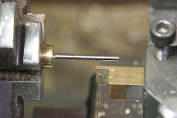
The valve ball is pushed up to the valve seat by a coil spring.The coil spring is made from 0.3mm stainless spring wire. It is coiled in the lathe with a 1.8mm dia. mandrel.
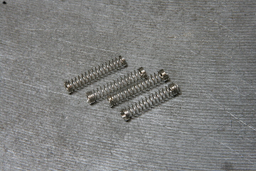
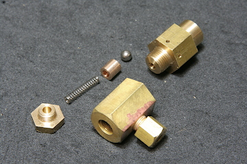
The coil spring pushes the ball through a phosphor bronze cup. The cup has small holes to release the back pressure.
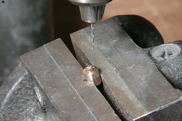
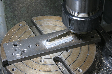
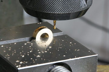
The pump body is made from brass hexagonal bars. The body is divided into two parts at the valve seat, so as to ease the valve sheet cutting. The two parts sandwich the base plate of the oil reservoir. The upper part has small cross holes to suck the oil.
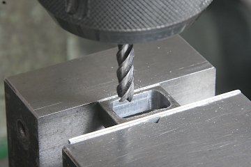
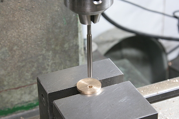
A stainless steel rod piston is inserted into the body. The rod has a rectangular strap window, which holds an eccentric sheave. The strap window is cut by an end mill. Note the window has a small hole at its top to pass an Allen key to tighten a set screw of the sheave.
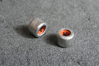
The photo shows the one-way clutches of 8 mm O.D. Its inner bearing could slip against the outer bearing in one direction. Set an arm around the outer bearing and swing the arm, Then, an axle in the inner bearing rotates in one direction.
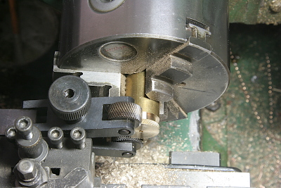
The arm is made from a 2mm brass sheet. Its round shape is cut on the rotary table. The arm bush is made from a brass round rod. Cut a slit, push the arm into it, and silver-solder them.
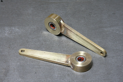
The finished arms. The one-way clutches are pushed into the arm bush.
A disc dial is set at the end of the axle. It is for the case of feeding the oil by hand. The dial is cut from a brass round bar and applied 'knurling'.
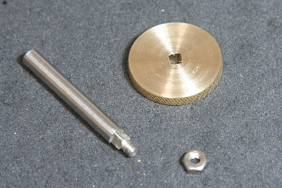
The dial has a rectangle hole at the center. The tip of the axle is cut rectangular, inserted into the dial, and fixed by a nut.
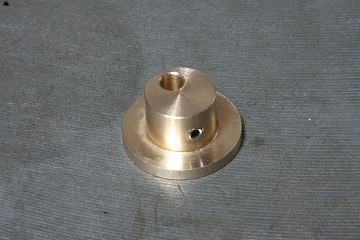
The eccentric sheave is made from a gunmetal round bar. Turn the flanged shape in the lathe. Drill and ream the eccentric hole. The sheave is fixed on the axle by a set screw. In order to prevent a slip of the sheave, I dig a small pit in the axle to catch the tip of the set screw.
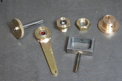
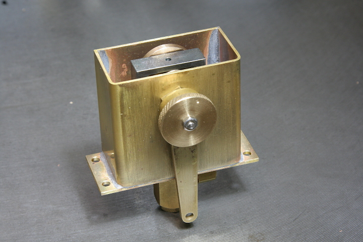
The photo shows all of the lubricator driving parts. The two parts at the center of the upper row are an axle bearing and its lock nut. The bearing has an o-ring, which is not for sealing but for adding rotational resistance to the axle. Otherwise, the inner and outer bearings always rotate together, and the axle never rotates.
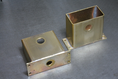
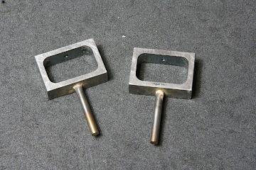
The oil reservoir is built from brass sheets. Shape the front and side faces by bending a plate in a 'U' shape, and then solder the back plate and the bottom plate. I employed a high-temperature soft solder, 'Comsol'.
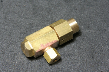
Finished lubricator. I made two for either side. Pour engine oil and confirm feeding without leakage. Next time, I will report mounting the lubricators and their driving components onto the locomotive chassis.