< Pressure Gauge and Others >
Here I decided to execute the test run before the completion of the exterior works of the engine. So I give high priority to preparing the components for the test run. I started to complete the fittings around the boiler.
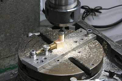
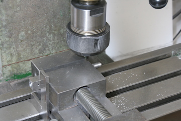
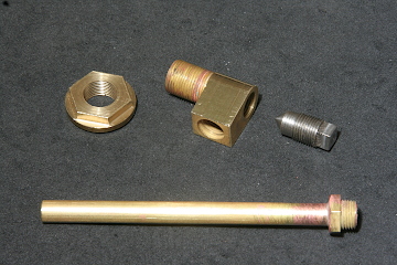
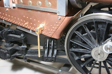
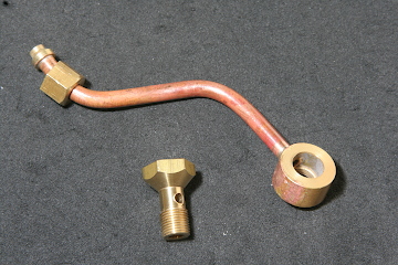
I made the blowdown valve for the blowdown bush on the right side of the firebox. The valve case is made of silver-soldered brass parts. It is finished on the rotary table.
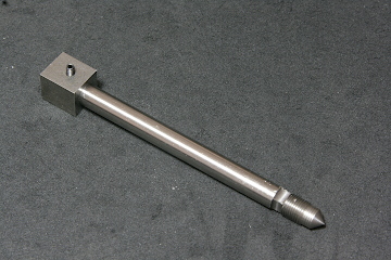
The screw valve has a square head. It is made from a free-cutting stainless steel round bar. After turning the valve profile, the square head part is milled every ninety degrees that are set by a square sleeve and a square gauge.
The photos show completed blow-down valve parts and their assembly on the firebox. The blow-down pipe consists of a brass tube and a bush made from a brass rod, silver-soldered together.
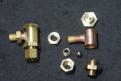
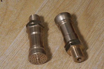
The check valves for the water supply to the boiler are made. The valve ball diameter is 1/4". The hole of the seat is reamed. The top cap has a projection at its bottom to limit the float of the ball.
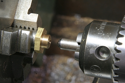
The valve seat is turned and burnished with a chromium ball. With a high-speed rotation, push softly by the ball for a moment.
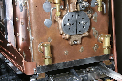
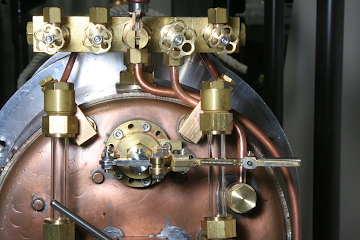
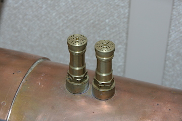
The check valves are set in the bushes at the lower part of the backhead. The left one is for both axle-driven pump and emergency hand pump, while the right one is for the injector.
I prepared the bypass lines between the water gauge tops and the steam turret. They are for releasing the trapped air in the water gauge glass.
In the steam turret, the valve with the biggest handle is the blower valve. The line from the valve goes through the boiler and is connected to the blast nozzle in the smokebox. In the photo, the copper tube behind the right side water gauge is that. Incidentally, the long tube behind the blower tube is the line toward the whistle.
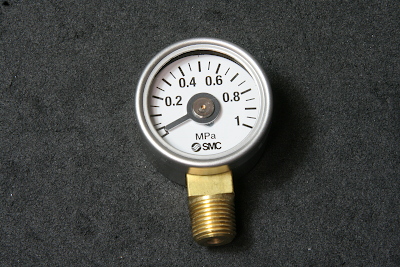
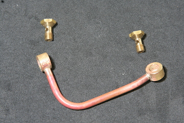
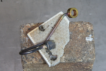
The pressure gauge I chose is not for model engineering but for industrial use. The diameter is 30 mm and its body is made by metal.
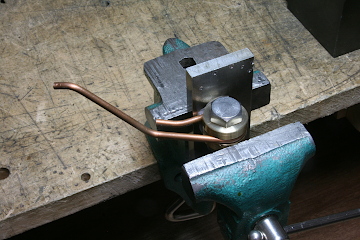
The tube for the pressure gauge has to be bent more than 180 degrees. In order to release the bent tube from the bending roller, I prepared a separatable bending roller as the photo shows.
The connection of the pressure gauge is 1/8" taper thread. As the cap nut could not have enough depth for tapping, I separated it into a nut and a cap. They are silver-soldered after tapping the nut. The cap nut is not a union link but a fixed link.
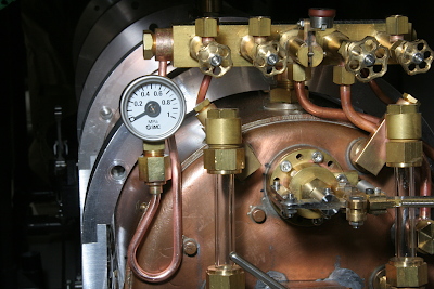
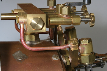
The pressure gauge with the tube is fixed on the backhead. Another end of the tube is connected to the left side face of the steam turret. Incidentally, the remaining three valves on the steam turret will be assigned to an injector, a donkey pump, and an electric generator. They will be made after the test run.
The safety valves were presented by You-san in Taiwan. I measured the working pressure with an air compressor and the result is 0.5 MPa.
The remained vital component for the test run, other than the tender, is the lubricator. I will report it next time.