< Painting Tender Chassis >
In order to prepare for the test run, I made some modifications to the tender chassis. Before that, I had painted the chassis. So I introduce painting and modifications in this order.
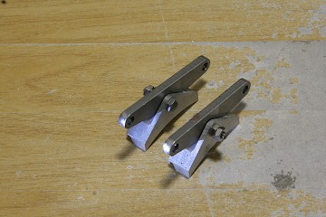
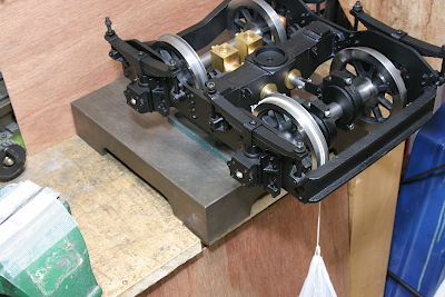
Before painting, I made a small improvement. As the brake shoes had been able to rotate freely around the hangers, the shoes had always leaned on the wheels and had tired themselves. So I prepared thin brass washers to adjust the friction force of the shoes so that the shoes can rotate by external force but hold their angles when released. The friction force is adjusted by a nut and locked by another nut.
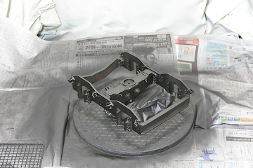
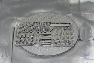
I utilized the usual polyurethane aerosol paint "matte black". Before painting, rust and dust on the parts' surface are removed with emery cloth. Note the parts are on a turn table in order to be sprayed from every direction.
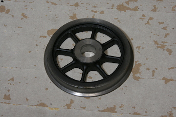
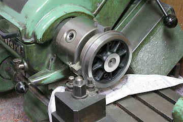
The wheels are once painted with easy maskings. After that, the tires are polished in the lathe.
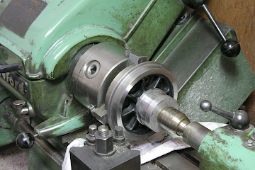
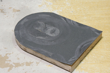
The bosses are polished with emery cloth on a wood plate. The plate is pushed against the boss by the tailstock. Finally, the wheels are glued on the axles with the Loctite 648.
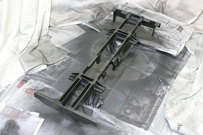
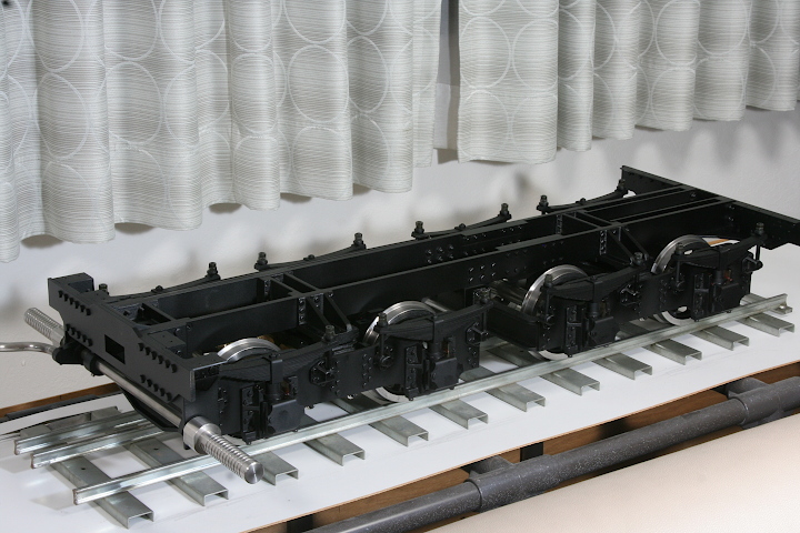
The frames are painted overall after assembly.
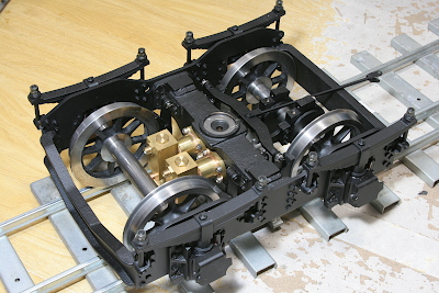
The trucks are assembled after painting. The brass axle-driven pumps aren't painted.
With a string and weights, the starting torque of the wheel with the axle-driven pumps is measured. The result is 0.14 Nm, while the calculated torque to feed water toward the working boiler is 0.61 Nm. It means that the mechanical resistance is less than half of the working force.
The whole parts are painted and assembled. After that, I did the following modifications.
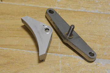
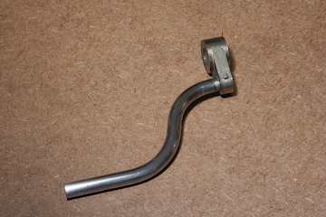
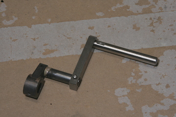
For space-saving, I had designed the footrest detachable, but I had forgotten the brake pedal. So I made the brake pedal detachable, too. The left side photo shows 'before', while the right shows 'after'.
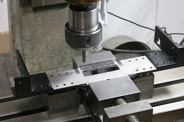
The engine and the tender will be connected with a drawbar. I extended the width of the drawbar window on the front buffer beam so as to enable the loco to pass on 7.5 meters radius S-curve.
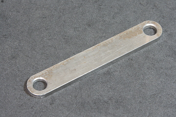
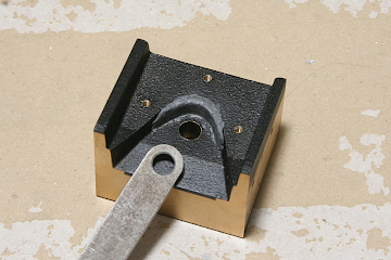
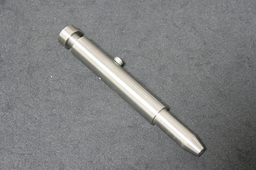
The left side photo shows the bottom view of the front casting behind the front buffer beam. A base plate is bolted on the casting and forms a pocket for the drawbar. The drawbar is normally held by the engine. When coupling, the drawbar is inserted into the pocket. The V shape of the pocket is for the positioning of the drawbar's back hole center. Note the V shape is corrected with metal putty. The right side photo shows the drawbar shaft to be inserted from the top to fix the drawbar.