< Tender Body 1 >
Usually, a tender utilizes its body as a water tank, so materials like brass or stainless steel are suitable for the tender body. In the prototype, there are thousands of rivets on the tender body. I will use copper rivets for them. Given that the body needs numerous holes drilled, I opted for brass as the body material.
Considering the weight of the human driver, 3 mm thick brass sheets are suitable, but they would make the tender heavy and difficult to construct. Therefore, I'm using 2 mm thick brass sheets and reinforcing the body with stainless steel angle frames beneath the driver's seat. The brass sheets will be joined using brass angles fixed by copper rivets or brass screws. The water tank will be sealed with soft solder after assembly. To create rounded corners on the back plate easily, I utilized a 1.2 mm thick brass sheet. This back plate will be bonded to the side plates in front of the curved corners. Additionally, the water tank features three breakwater plates to prevent water fluctuations. The tank can be separated by a central wall to halve its volume. An overflow pipe will be installed to limit the maximum water level. The design of the tender body is based on these assumptions.
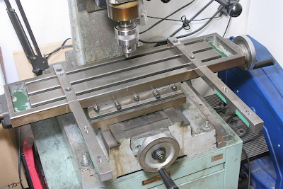
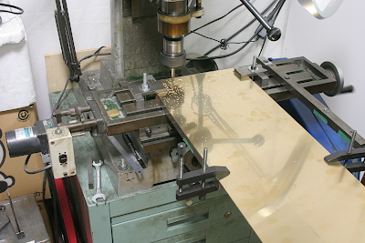
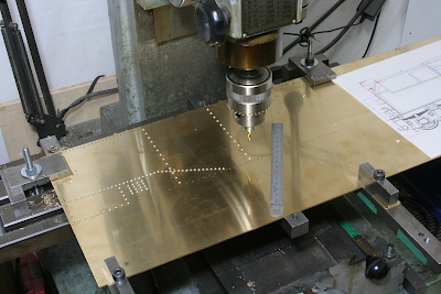
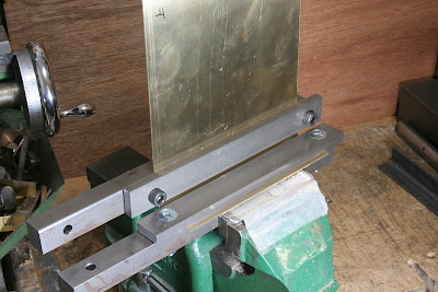
The brass sheets will be drilled and milled using the milling machine. To accommodate the wide sheets on the narrower milling stage, I extended the stage with two vertically placed flat bars.
These two flat bars were cut simultaneously. Steps were cut in front of the bars to ensure clearance for an endmill tip. Pairs of holes were drilled and reamed for parallel pins. The bars will be secured on the milling stage, maintaining exactly parallel and vertical alignment, utilizing a dial gauge.
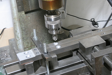
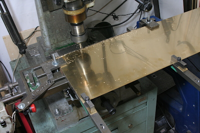
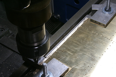
The side plates were cut from a 2 mm brass sheet and milled on the top and bottom edges. After finishing an edge, I reversed the sheet and align it parallel to the pins.
Also, the front and back edges were milled. Aligning the finished bottom edge with the flat bar will ensure that the milling line is vertical to the bottom edge.
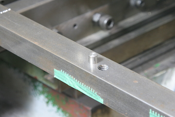
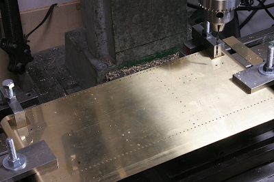
For rivet holes, I employed 1.6 mm diameter copper rivets. As the 1.6 mm drill hole is slightly tight for the rivet, I utilized a 1.7 mm drill. The hole positions will be determined by X-Y coordinates of the milling stage. A dial rotation will move the stage by 2.5 mm, so I chose rivet pitches that are multiples of 2.5 mm. Start with a thin center drill and follow with the 1.7 mm drill. It required three different setups as the side plate is more than twice the length of the milling stage's movable range.
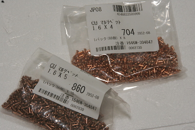
I prepared two types of rivets with varying lengths. One type is for individual use as dummy rivets, while the other type is for fastening the brass angles. With over 1500 rivets needed for the tender, it's evident that drilling these holes will be time-consuming.
For the singly used rivet holes, I countersank them from the inside to allow the rivets to be flattened into place. Incidentally, countersinks are also necessary on the brass angles where they'll be fastened with rivets.
The back plate is cut out from a 1.2 mm brass sheet and bent on both rounded corners using a round bar and a steel angle. Due to spring-back, the corners might end up being more than 90 degrees.
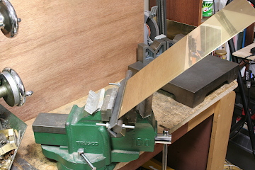
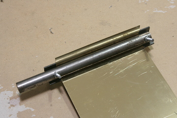
As shown in the photo, I performed the additional bending. Each flat part was clamped between two flat bars, while the round part remained free. To achieve the desired body width, I'll scribe and bend one side and calculate the bending position for the other side based on the result.
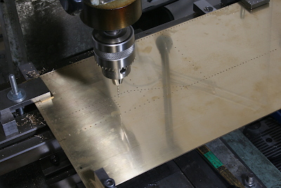
I delayed drilling the back plate until after bending, as the true centerline can be marked based on the bending outcome.
I created a step along the rear end of the side plate, allowing for overlap with the back plate. This involved cutting 1.2 mm into the 2 mm thickness to achieve a flush seam.
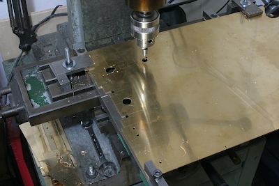
Similarly, the bottom plate was cut from a 2 mm brass sheet. The photo shows the process of creating a hole using a hole saw.