< Leaf Springs and Buffers >
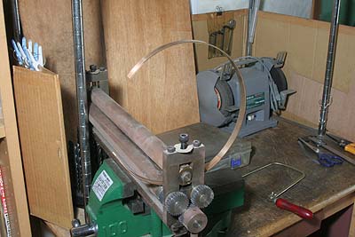
The leaf springs are made from phosphor bronze band plate that I used for
C53, rolled to a desired diameter by the handmade bending roll.
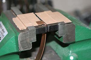
The top plates have to be foiled at both ends. I foiled it larger with hammer and vise, and then cut the surplus with a fine sanding tool.
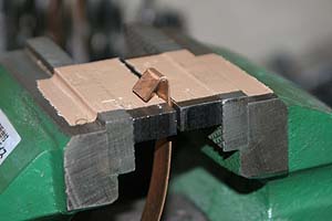

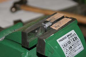
The spring bracket is bent from a steel flat bar with a jig that I used for C53's leaf spring.
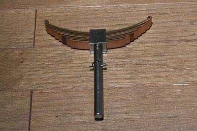
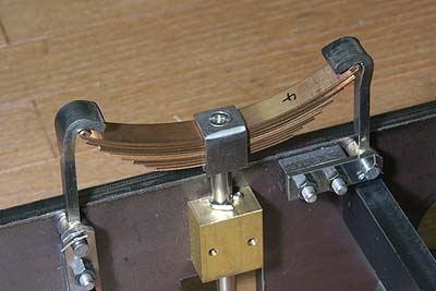
The photo shows assembled leaf spring. The spring plates are gathered and bolted onto the top of the spring shaft. Currently the length of the shaft is larger than the design. It will be determined when the loco completed. Note a split pin in the middle of the shaft. I will explain about it later.
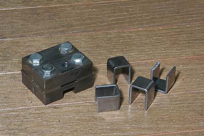
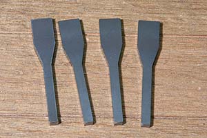
The spring hooks are made from laser-cut steel plates. They are bended with hammer and vise, too.
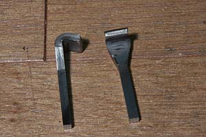
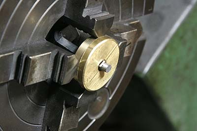
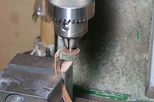
So as to braze a bush at the hook bottom, the hook bottom is turned in the lathe. In order to clear the bent part, the hook is chucked with a simple brass collet. I had to turn them after bending them because the total length after bending could not be expected precisely.
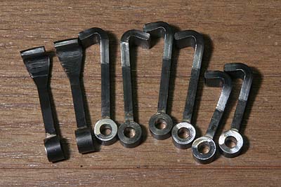
The bushes are made from silver steel round rod and silver soldered onto the hooks.
The leaf spring and the hooks are mounted into the chassis. Now the split pin secures the lower limit of the leaf spring height. If there isn't, when you lift up the loco, the leaf spring drops and the hooks are released. When the loco is running, the split pin will slightly float over the brass block.
As I obtained cast iron parts for buffers, I completed buffer beams with necessary parts. The buffers don't have actual use but I made them active with coil springs. The buffer post has a stepped hole inside. A stopping plate is bolted at the bottom of the plunger. Then the plunger with plate is push by a coil spring.
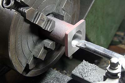
The post is turned from its back. Starting from the bolting face, the stepped hole is drilled and expanded with a large boring tool.
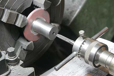
The plunger neck is turned to a loose fit to the post. And then the hole for a bolt is opened.
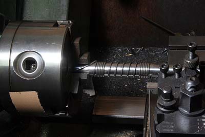
The coil spring is coiled in the lathe. I employed 1.6mm stainless steel wire specified for coil spring use. Typical coil spring has clockwise spiral but my spring has counter clockwise spiral because I usually coil them from the lathe head stock.
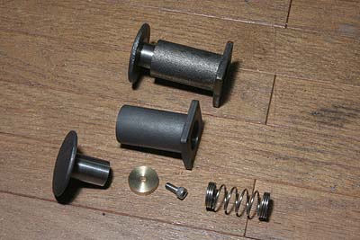
The photo shows before and after assembly of the buffer. The stopping plate is made from brass round bar.
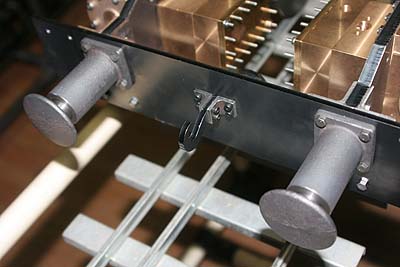
The buffer is mounted onto the buffer beam utilizing buffer beam fixing bolts. The photo shows the front buffer beam. Note a coupler hook in the middle of the buffer beam. It is a laser cutting part held between two angles.
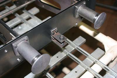
It is the rear buffer beam. It has a draw bar holder made of steel angles, instead of the coupler hook.
The chassis is almost completed. It looks odd for a locomotive because the wheels are hidden between the frames.
