< Rods and Pumps >
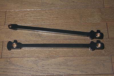
The coupling and connecting rods are prepared as laser-cut parts. As they
will be painted instead of burnished, I don't care much about their finish.
I only ground their longitudinal edges with a sanding stone.
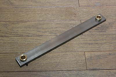
I prepared a jig to take the loco wheelbase. It has two brass bushes. One is normal and the other is eccentric. The eccentric one can be fixed with a set screw. Size of the bushes is the same as the rod bushes. (O.D.=13mm, I.D.=10mm)
On a flat surface, two crankpins are set truly horizontal with suitable height stands. Then the wheelbase is taken from the crankpins.
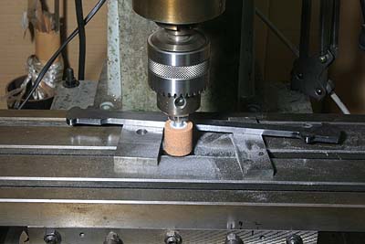
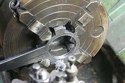
The wheelbase is traced on the coupling rod as follows. Drill one 13mm
hole in the rod. Pull out the normal bush from the jig and push into the
rod. Line up the normal bush in the rod and the eccentric bush in the jig
and put 10mm round bar through. Clamp together and drill another 13mm hole
in the rod through the jig.
The bushes for the rods are made from phosphor bronze bar. Their O.D. is 13.05mm for press fitting into the rod, while the I.D is 10.1mm to ensure slight play around the crank pins. Finally the hole for lubrication is drilled from the top through the bushes.
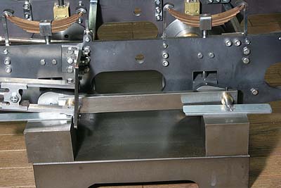
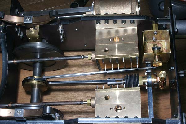
The rods are set in the chassis. I prepared spacing sleeves and fixing rings made from silver steel round bar.
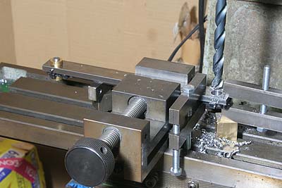
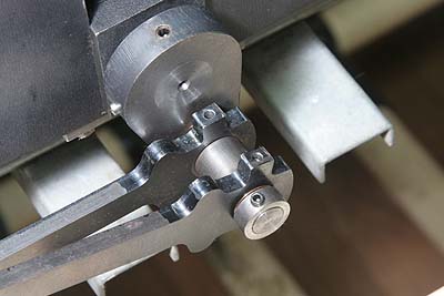
Now you can determine the distance between the crosshead and the piston. The piston rods are fixed into the crossheads with taper pins. The photo shows taper-reaming of both parts for a taper pin.
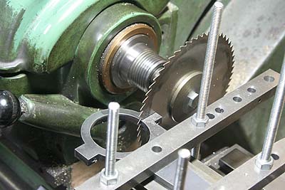
Next, I made eccentric straps. you need one for the axle driven pump and 4 for the valve gear. They are laser-cut from 6mm steel sheet. Semicircle of the straps are cut off by metal saw. Cut faces are trued up by end mill. And they are assembled with screws. You had better drill holes for screws at first, before cutting of the semicircle.
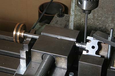
The bore for eccentric is finished in the lathe. This is the valve gear strap.
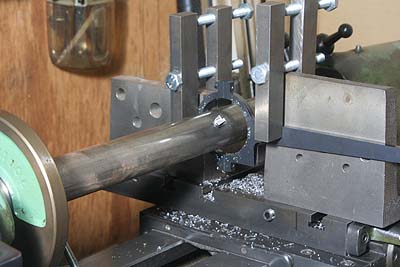
In case of the pump strap, the arm is longer than the lathe's center height. So I finished them with a boring tool between the lathe centers.
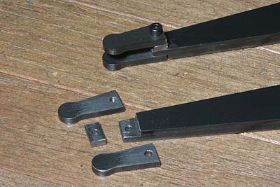
The fork end of the valve gear strap is offset, because two straps share one expansion link. The photo shows how to construct the offset fork. It consists of laser cut parts and steel flat bar. They are bolted together and silver soldered. At the moment, hole for pin is not opened yet.
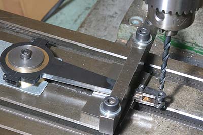
All of the valve gear straps must have exactly the same axle distance. I ensured it by a fixing jig on the milling table. The hole is center drilled and drilled through.
The axle driven pump and the lubricator are mounted in the chassis. These are OS products. The axle driven pump is bolted into a stretcher just after the front buffer beam. The pump strap has fork end of a pair of parallel plates and linked to the pump ram. The lubricator is bolted onto a frame through hexagonal columns. It is driven also by the pump strap through a reach rod.
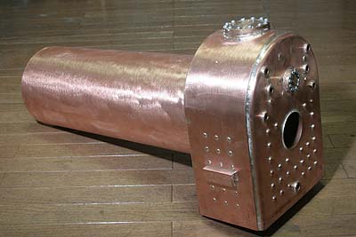
The boiler was delivered eventually from Western Steam Model Engineers.
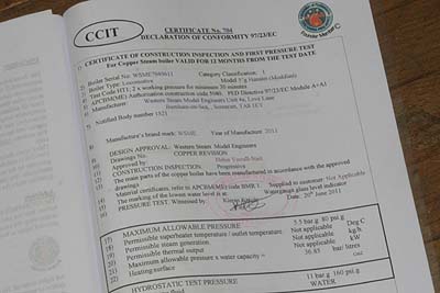
The hydrostatic test certificate shows it was tested under 160psi, so the
operating pressure is 80psi.
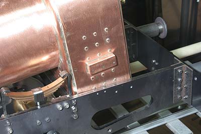
I tried to insert the firebox between the frames and failed due to the
projection of the side stays! My design allows only 1mm play in each side
of the firebox. But the firebox width was finished 1mm oversize. I know
1mm error is reasonable for such kind of copper products. In short, it
is an issue of my design!
I don't want to file off the projection because it possibly causes leakage. So I'm going to cut shallow recess inside of the frames to clear the side stays, at the next chance of disassembling the chassis.