< Valve Gear >
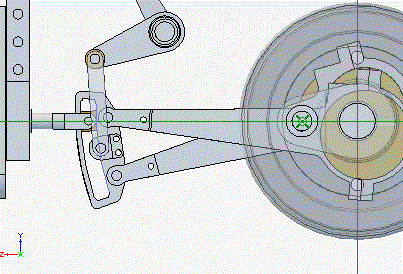
I designed the valve gear and checked the design with 3D-CAD. Due to swing
of the expansion link, you can see the die block moves up and down in a
certain amount. And the link pin towards the strap also moves up and down
from the valve spindle height. They cause error of the valve motion.
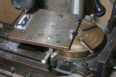
The expansion links are laser cut parts. Only their recesses are finished by end mill. The size of recess arc is beyond the rotary table stage, so I extended the stage with a thick steel plate. The expansion link is bolted onto the plate utilizing the holes for the link pins. Note 1mm aluminum sheet is packed between the expansion link and the plate, so as to clear end mill tip.
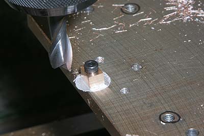
The die blocks are also finished on the plate. A suitable phosphor bronze rod is parted desired thickness, bolted onto the plate and finished the same radius as of the expansion link.
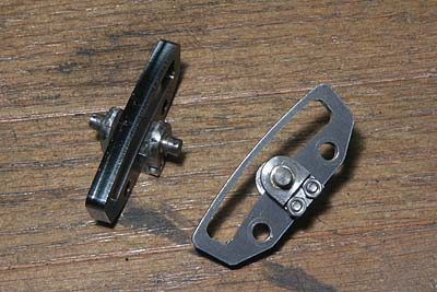
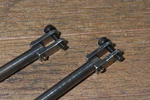
Pair of the trunnion are made from steel rods and bars. They are cut, silver-soldered and assembled onto the expansion link.
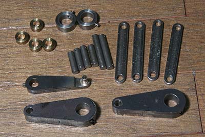
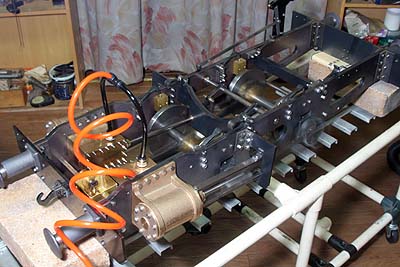
The photo shows other parts for the valve gear. The lifting arms and the reversing arm are laser cut. Others are made from steel rods and bars.
Fork of the valve spindle is made from two parallel plates, bolted and silver soldered. In order to avoid interference with the inner motion plate hole, neck of the fork is thinned in the lathe.
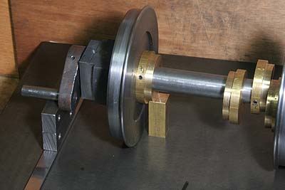
The each eccentric's angle was adjusted beforehand. On the flat surface, The crank pin and each eccentric are set in correct angles with suitable stands and the set screw of the eccentric is tightened. After valve adjustment, I'm going to secure the eccentrics with taper pins.
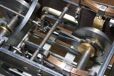
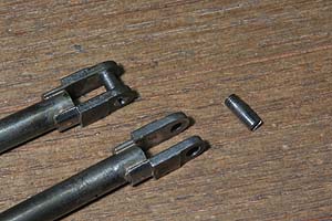
The valve gear is assembled. The weighshaft is 10mm steel rod and held between two phosphor bronze bushes in the main frames. The lifting arms are secured only with set screws but I drilled small recesses on the weighshaft to catch the set screws' tips. The reversing arm will be silver soldered on the weighshaft after the valve adjustment. All of the connecting pins are plane rod and secured with tiny cotter pins.
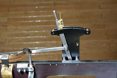
The cab reverser is a product of OS. It is bolted on the frame through suitable spacer.
Before valve setting, the dead centers of the driving wheels are found with conventional method. I made a center punch mark in suitable point of a stretcher to catch dividers' leg, and scribe on the wheel tread.
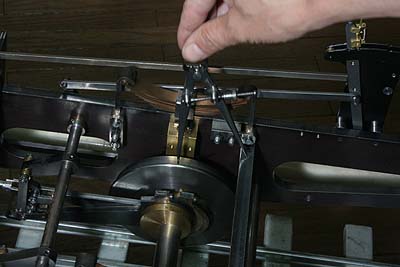
The slide valve is set to be equal travel from the center at front and rear dead centers. If your design and construction are accurate, the valve ought to start opening the port just at both dead centers. If not, you should start over from the eccentric angle setting.
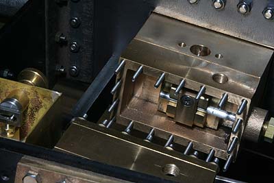
Now is the time for the compressed air test. The leaf springs are removed. The axleboxes are set in the center height with suitable packing on the horn stays. Screw holes for drain cocks are covered with screws. The steam chest is connected to the air compressor through plastic tube with one-touch air connecting plugs.
I started without lubrication, then the valves didn't land on the port
faces. After pouring oil into the steam chest, the engine started running
at the air pressure less than 0.1MPa. I found the length of expansion link
window is not enough and the die block pushes up the link at its top. So
I expanded the window with a file.
In the movie, the cab reverser is set a little down from "full forward",
in order to get clearer blast noise. With successful valve setting, four
blast noises sound in equal length and intensity.