< Cylinders and Pistons >
 I reported that I modified my engine from
s-v to p-v. I will report about that in the
next time. Here I introduce the cylinder
blocks, cylinder covers and pistons. This
is a sequence to the page "Wood Pattern
for Cylinder Block".
I reported that I modified my engine from
s-v to p-v. I will report about that in the
next time. Here I introduce the cylinder
blocks, cylinder covers and pistons. This
is a sequence to the page "Wood Pattern
for Cylinder Block".
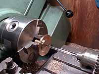
Bolting face to the frame is finished in
the four-jaw chuck.
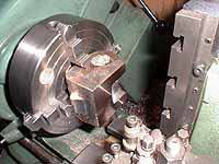
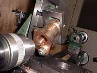
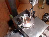
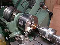
The two bores are opened out from backside
of the cylinder. First, the steam chest bore
is opened to final diameter. Note a brass
disk glued around the main bore for scribing
center. I have to report a pair of angleplate
and faceplate doesn't always give me a true
square! It is worth testing by D.T.I. just
before turning.
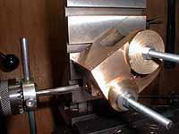
Next is the main bore. Only screws between
the faceplate and the angleplate are slackened
for centering, so as to keep two bores parallel.
To minimize chattering, I prepared small
boring tool with fat hexagonal steel bar.
In this setting, face for the back cover
is also finished. The opposite side (for
front-cover) can be finished in four -jaw
chuck, because the front face doesn't need
to be strictly square to the bore.
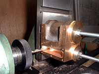
Boring ports. The port has tilt in two directions.
The angleplate between the vertical slider
and the job can adjust direction. The cutting
procedure is:
1) mill end of the port to be square
2) center and drill a series of holes into
the steam chest
3) remove walls between the holes by a long
endmill
The steam inlet is drilled and tapped.
The exhaust recess is formed by "rough-cut"
endmill, and the passageways to the steam
chest bore are slot-drilled in both ends
of the recess.
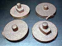
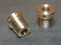
Gunmetal castings for cylinder covers. Particularly
the back covers need following accuracy.
1) All of center hole, inner register, chamber
for the O-ring and thread for gland have
to be concentric.
2) bolting faces for slide-bars should be
parallel and same distance from the center.
I prepared a special jig to overcome such
difficulties.
Chucking with outer spigot, the inner resister
is cut and the center bore is drilled and
reamed.
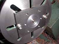
The special jig to finish outer side of the
cover. After the jig was fixed firmly onto
the faceplate, the center pin and the inner
face are trued up.
When the cover is mounted onto the jig, the
inner resister and bore become concentric
and square to the lathe spindle. Then the
O-ring chamber is bored and threaded. I left
diameter of the O-ring chamber smaller than
the thread. So when a gland is screwed into
the end of the thread, the chamber will maintain
correct depth.
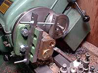
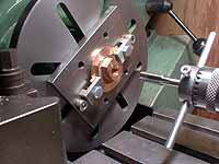
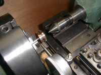
The jig is mounted on cross-slider with a
suitable packing. Then the bolting face for
slide bars are cut to the correct depth.
The job is just rotating 180 deg. in the
jig without moving the saddle. Note a guide
bar on the tail stock to ensure 180 deg.
rotation, by pushing onto a finished surface.

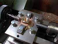
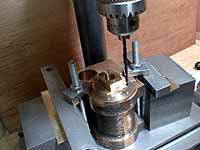
The side arc of the cover is milled in the
jig mounted on a rotary table. Such an operation
as cutting a side and a bottom at a time,
has a chance to capture the tool and spoil
the job! Please take care.
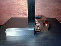
I also prepared a jig to drill screw holes
in the covers. The tapped holes in the cylinder
are copied directly from the covers. Particularly
for the back covers, the slide bar seatings
are kept square to the frames by a try-square.
The piston glands of brass. If you adopt
hexagonal shape here, you have to confirm
that your spanner can slip into the space
between the slide bars.
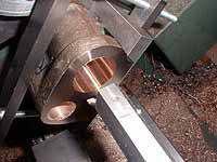
The piston is made of phosphoric bronze.
Before finishing outer diameter, the piston
rod is pulled into it. Deeper half of the
hole and the same length of the rod end are
threaded for pulling work. The remainder
is adjusted to press-fitting diameter. Once
the rod end catches up the thread in the
hole, the rod is automatically pulled into
the hole by turning lathe spindle by hand.
The spindle is chuck with four jaws and centered
with a dial gauge to ensure concentricity.
Then the diameter of the piston is finished
to a nice sliding fit to each cylinder.
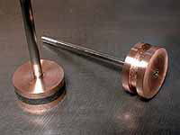
The groove of the piston is filled with graphited
yarn.
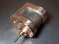
Assembled cylinders waiting for the piston
valves.
| TOP | BACK | NEXT |