< Heat Exchanger >
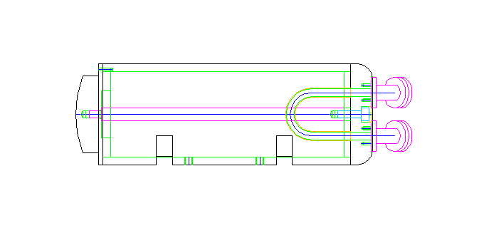
JNR steam locomotive has a heat exchanger in the feedwater line coming from the donkey pump. The C53 has a heat exchanger installed under the front deck. In the model, it is a dummy, but water is actually passed through the piping from the donkey pump, allowing water entering from the inlet to flow directly to the outlet. The water inlet and outlet are located on the right end plate, and a U-shaped pipe inside short-circuits the flow. In the actual machine, the heat exchanger is covered with a jacket, but in the model, only the jacket is represented using aluminum alloy pipes. Of the two end plates, the left one is made from an aluminum alloy disk, while the right one is made from a brass disk since it requires silver soldering of a copper U-tube. The right end plate has no fixing bolts on the outer perimeter and is secured by pulling the center part with a stainless steel rod from the left end plate.

The body of the heat exchanger is made of an aluminum alloy pipe with an outer diameter of 65mm, which is the same material as the air reservoirs. Both ends are finished using a fly cutter.
In the prototype, part of the jacket overlaps the lower part of the main frame, so notches are made in the pipe using an end mill to replicate this.
At this stage, the mounting process to the main frame is performed. To drill holes without removing the front buffer casting, a jig was prepared and used to transfer and drill the holes.
The heat exchanger is fixed under the front buffer casting using brackets made from processed steel angles.
The end plate made of aluminum alloy is fabricated. The stepped part for insertion is processed in the lathe, and the entire chuck is moved to the milling stage to drill fixing holes along the perimeter. The center was marked with a cross during lathe processing and used as the origin for drilling holes based on XY coordinates to align the step and hole centers.
Returning to the lathe, the remaining tasks include drilling threaded holes for inserting round bars.
Reversed, then the surface is finished with a rounded edge. Step cutting is performed, and the surface is smoothed with a file.
The completed end plate is inserted into the main body, countersunk the main body through the end plate with a drill tip, remove the end plate, drill and threaded holes on the body.
Next, the brass end plate is processed similarly, with step cutting for rounded edges and smoothing with a file.
A counterbore process is performed to attach both flanged short pipes to the water inlet and outlet. It is eccentrically chucked with a four-jaw chuck and finished with a boring bar.
The entire chuck is moved to the milling stage, and threaded holes for attaching the flanged short pipes are drilled. The center of the each flange was determined using a D.T.I.
A U-shaped copper tube is silver-soldered to the inside of the end plate. The ends of the U-shape are bent sideways to avoid the central round bar.
Before attaching the brass end plate, the stainless steel round bar visible at the center is threaded into the aluminum end plate and has a threaded hole on the brass side, allowing it to be fixed with bolts from the outside.
After attaching the end plates, An Allen key bolt is used to secure the center. An additional screw was added in an inconspicuous place to prevent rotation.
A double flange short pipe has a structure in which two flanges oppose each other at a 45-degree angle with a curved pipe. The curved pipe section poses a challenge, as even annealed brass rod or copper tube cannot be bent neatly at such a steep angle. Therefore, lost-wax casting is used for this part. However, the flanges on both sides are made from brass round bar, assembled with silver soldering. As usual, wax patterns were milled using Modela and asked for casting.
The flanges were made by cutting brass round bar and finishing both sides. Fixing holes were drilled at this stage.
Threaded holes were drilled into the cast parts, and the flanges were fixed with brass screws, followed by silver soldering one side at a time. In the left photo, the hole-like marks on the cross-section of the cast parts are center punch marks used to ensure a small gap at the joint surfaces.
The heads of the brass screws were filed down, and holes were drilled through from both sides. However, drilling perpendicular to the flanges would cause the outer wall to thin at the bends, so holes were drilled at a slight angle of about 5 degrees. During vice-chucking, the angle was adjusted using a smartphone level app. To prevent flange deformation due to strong clamping, thick aluminum plates were used for protection. After milling a horizontal surface with an end mill, holes were drilled sequentially using a center drill and then a regular drill.
The completed double flange short pipes have one side with threaded holes and the other with plain holes. The threaded holes are on the side where pipes with other flanges are connected, and the plain holes are for fixing to the heat exchanger's end plate.
When attaching the double flange short pipes to the brass end plate, a brass disk is inserted into the center bolt hole to conceal the bolt head. The disk is held in place by the flanged short pipes.
The heat exchanger is now complete. In the actual machine, many steam pipes are connected to the central part, but since they are on the inner side of the main frame, they are omitted this time.
In the mounted state, the clearance with the leading wheels is tight, but according to the design, it barely avoids contact when passing through a 7.5R curve.