< Brake Valve 1 >
The driving and coupled wheels are braked using a steam brake. While the brake cylinder was already completed, work on the brake valve had yet to begin. After considering which type to use, a variable-pressure brake valve featured in the guide book by Martin Evans was found to have an intriguing structure, so it was decided to base the design on this concept. To preserve steam heat, the brake valve was directly mounted onto the steam turret on the backhead, and the steam piping was routed between the boiler and boiler cleading to the brake cylinder. A cross-sectional diagram of the brake valve is shown.
The left side of the diagram shows a top-down cross-section. The valve mechanism is arranged in two series—on the right is the braking valve, and on the left is the release valve. Steam from the steam turret enters the braking valve from the top right. The braking valve uses a ball valve pressed by a spring and plunger to stay closed. When the handle is turned, the cam rotates, loosening the spring, which reduces the seating pressure of the ball valve. When the pressure becomes lower than the boiler pressure, the ball valve opens. As steam flows in and pressure on the cylinder side increases, the pressure differential decreases, causing the ball valve to close again. By properly designing the spring, the cylinder pressure can be freely adjusted from atmospheric pressure up to boiler pressure.
As for the operation of the release valve, when the handle is returned to the 9 o’clock position, the braking valve closes, and the release valve opens, releasing steam in the cylinder to the atmosphere (the diagram shows the release state). The diagram on the right is a right-side view showing the section of the release valve. Among the two ports on the right side of the diagram, the upper one connects to the cylinder and the lower one to the atmospheric exhaust line. The port on the left side is for connection to the brake pressure gauge.
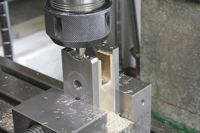
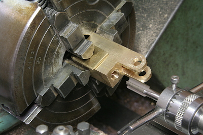
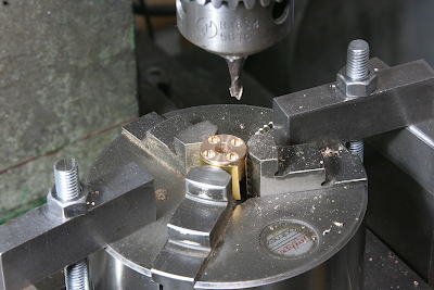
The main body is machined from a brass block. The photo shows the machining of the fork section that holds the handle shaft. To prevent deformation during machining, both sides are supported by flat bars.
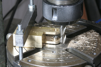
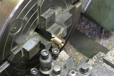
The shape of the fork section was finished by machining the curve using a rotary table.
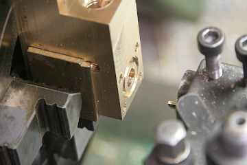
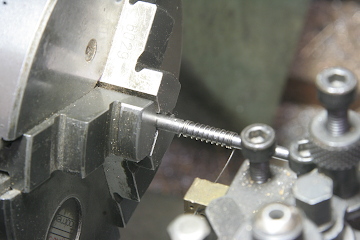
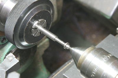
Next, necessary hole drilling is carried out. The photo shows threading a tap into the valve chamber of the release valve.
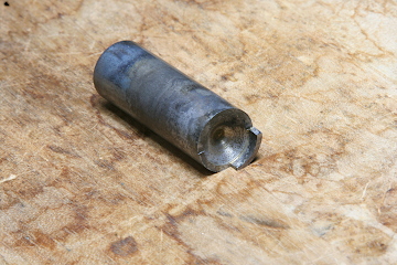
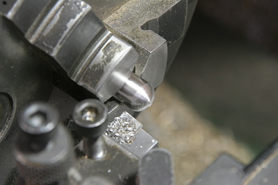
The part that connects to the steam turret is sealed with an O-ring. To machine the ring-shaped groove for the O-ring, a handmade cutting tool like the one in the photo was created. High-carbon steel was shaped as shown, then hardened and tempered. Using this tool, the ring groove is cut from the front in the lathe.
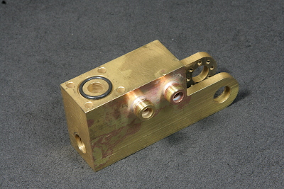
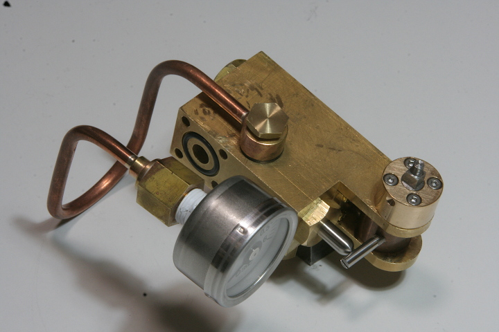
The required nipples for connections were fabricated and silver soldered. The assembly is completed. The photo shows the O-ring installed for the steam turret connection.
The cylindrical component supporting the handle shaft was made from a gunmetal round bar. A counterbore was machined to allow it to be screwed into the fork section.
An O-ring retainer to fit into the braking valve hole was created. Due to the fork structure, the head shape is restricted and thus made rectangular. It is fixed at the four corners with screws to the main body.
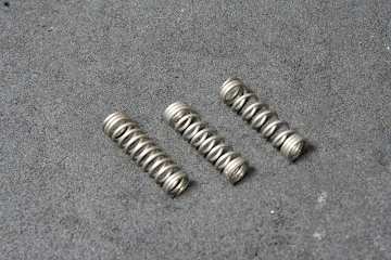
The coil springs were made as usual using the lathe. Three types were prepared for the braking valve with varying winding pitches to adjust strength. A coarser pitch (fewer coils) results in a stiffer spring.
The spring pocket for the braking valve was made from free cutting stainless steel round bar. The tip, which is pressed by the cam, was finely stepped and finished into a curve using a file.
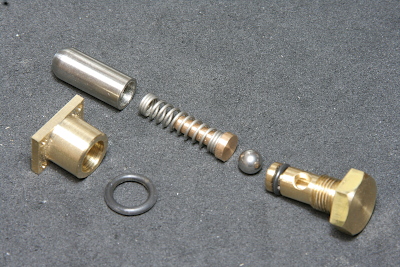
These are all the components for the braking valve. The plug forming the valve seat is also sealed with an O-ring. Only the plunger pressing the stainless steel ball valve is made of gunmetal.
The release valve body is a specially shaped shaft, made by turning an free cutting stainless steel round bar in sequence from the tip.
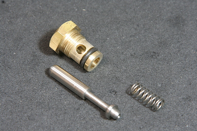
These are all the components of the release valve. The valve seat is the tip of the brass plug, and the tapered part of the valve shaft makes contact to close it. The narrow section forms the steam passage. When the valve opens, steam is released through the side hole in the plug to the atmosphere.
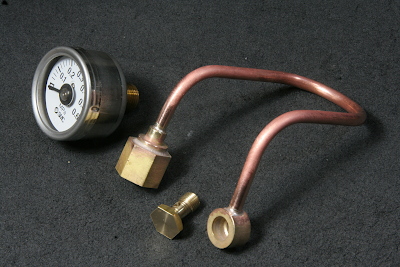
The pressure gauge is the same type as used for the boiler, but with a maximum pressure of 0.6 MPa and a rear-facing connection instead of a bottom one. The connection is PT1/8, and a dedicated taper tap was made for the union nut. The procedure is the same as for the boiler pressure gauge.
This shows the assembled parts up to this point. As for the brake valve, the only remaining component is the handle. The brake cylinder is also planned to be equipped with a drain valve and a lubricating valve.