< Cab 3 >
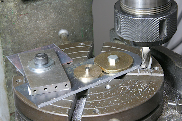
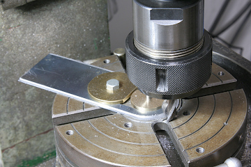
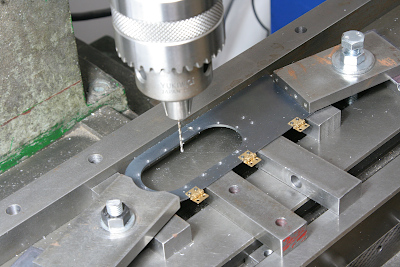
The front door was laser-cut from 1.6 mm steel plate, but to better represent the thinner appearance of the prototype, a stepped recess was machined around the perimeter down to 0.8 mm thickness. This operation was carried out using a rotary table.
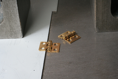
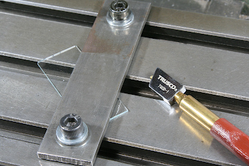
For the hinges, I used miniature brass hinges intended for dollhouses. To match the 0.8 mm step in the door, one leaf of each hinge was hooked over a 0.8 mm plate placed on a surface plate and then pressed from above to form the required offset.
The front cab panel was then drilled and tapped to accept the hinges.
With the hinges installed, the door was mounted to the front panel.
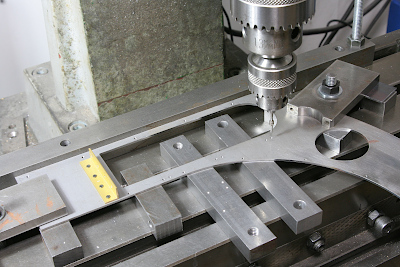
Next, holes were drilled in the door for attaching the window frames.
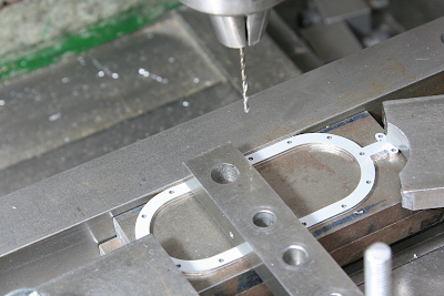
The window frames were laser-cut from 0.8 mm material and drilled to match the mounting holes. Frames are fitted to both the inside and outside of the door, sandwiching the glass between them. One side uses clearance holes, while the other side is tapped for screws.
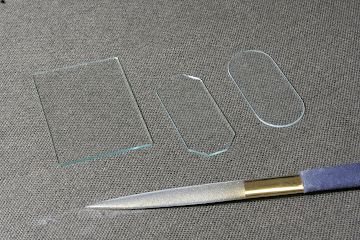
The glass was made from 1.2 mm sheet glass. It was first cut into a rectangle with a glass cutter, the four corners were trimmed away, and the piece was then shaped into an oval using a diamond file.
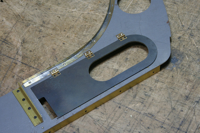
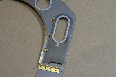
Because the glass is thinner than the door thickness, a retaining plate was embedded on the inside of the door, as shown in the photo, to press the glass forward against the outer frame.
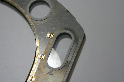
The door with the glass and window frames installed is shown here.
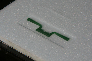
The door handle was produced using the lost-wax casting process. I machined the wax pattern on a Modela mill and sent it out for casting. To reduce cost, the two handles were combined into a single casting.
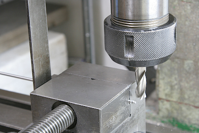
The photo shows the indexing operation on the tip of the handle’s rotating shaft. A square bar was fixed to the left end of the round shaft blank, and using a machinist’s square as a guide, the part was rotated in precise 90-degree increments for machining.
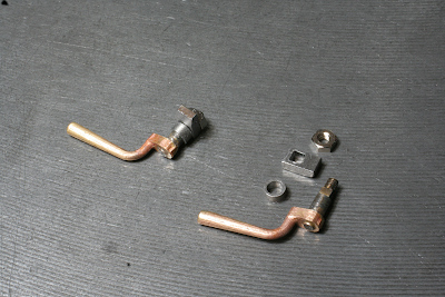
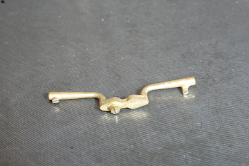
Shown here are the completed handle assembly and its disassembled components. The handle and shaft are silver-soldered together. A cylindrical spacer is fitted at the tip of the shaft, and a notched piece is installed over it. The square hole in the notch mates with the previously machined square section of the shaft.
With the handle installed on the door, rotating it outward disengages the notch mechanism, allowing the door to open.
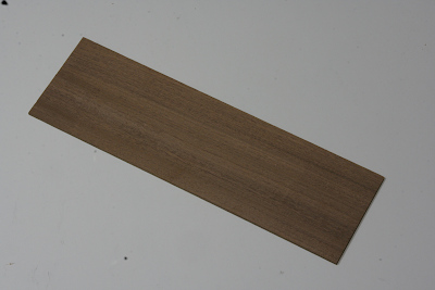
With the front panel work completed, I returned to the cab sides to fabricate the sliding side windows. As on the prototype, these are wooden-framed sliding windows. The frames were made from 3.5 mm thick teak.
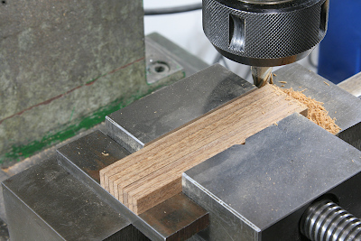
The stock was cut to width with a fret saw, then trued on a surface plate using sand paper, and finally brought to final length with an end mill. Multiple identical pieces were finished together for consistency.
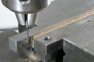
A slot to receive the glass was cut using a 1.2 mm end mill.
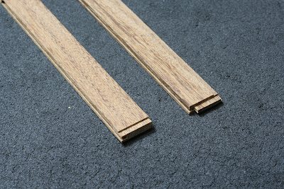
The corner joints were designed so that the frame members interlock. The photo shows enlarged views of the two different end configurations.
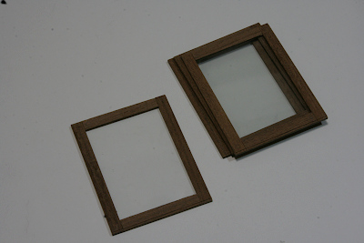
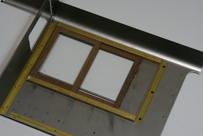
The 1.2 mm glass was cut into the required rectangular shapes using a glass cutter, and the wooden frames were assembled. At this stage, the frames remain dry-fitted; they will be varnished individually before final gluing.
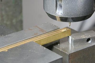
The window rails mounted to the side panels were made from brass square bar. Grooves for the sliding windows were milled using an end mill.
Finally, the sliding windows and rails were installed on the inside of the side panels. Grooved rails were mounted at the top and bottom, and the front and rear ends were closed off with angle stock.