< Cab 2 >
Once the basic assembly of the cab was complete, I moved on to the finer details. The first task was fabricating the handrails mounted below the cab side windows. The left and right supports were prepared using the lost-wax casting process. As usual, I machined the wax pattern by the Modela and sent them out for casting. The pattern was designed to produce all four required parts in a single piece.
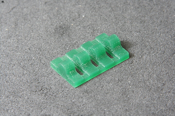
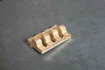
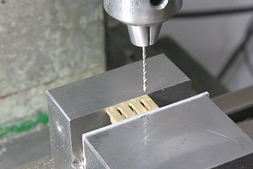
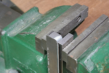
After casting, all four parts were drilled together, then separated. Holes for the handrails were opened next. Because there was very little depth available and the bottoms needed to be square, these holes were cut with an end mill rather than a standard drill.
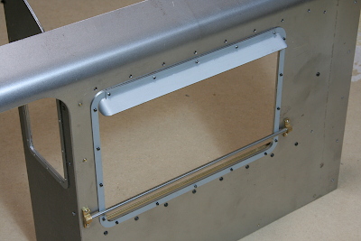
The handrails themselves were made from free-cutting stainless steel round bar and inserted into the lost-wax cast supports. The assembly was then mounted to the side panels. The panels were tapped and the parts secured with miniature precision screws.
The destination sign frames mounted on the side panels were also made using lost-wax casting. Two frames are required on each side, so they were formed as left–right pairs. Both front and back surfaces were finished so that an actual destination plate could be inserted.
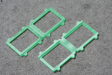
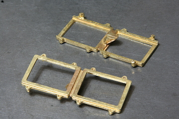
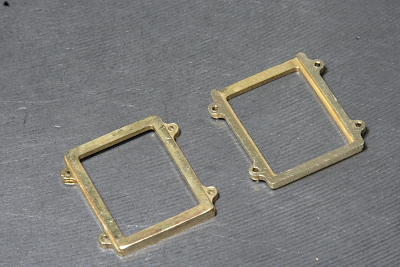
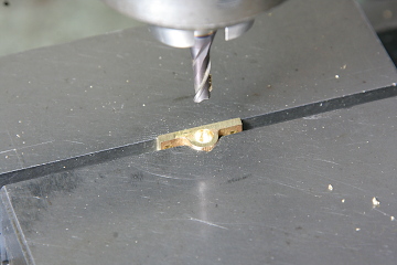
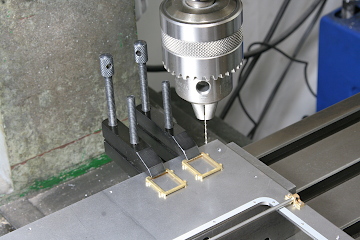
After separating the castings and removing any flash, the mounting holes were drilled. Shallow recesses had been formed in the castings in advance, allowing the holes to be drilled directly without center punching.
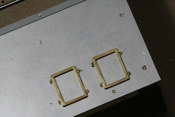
To mount the frames, threaded holes were made in the side panels. Each frame was temporarily fixed with a single screw, clamped in position, and then the remaining three holes were transferred and drilled.
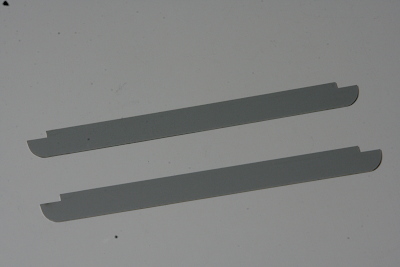
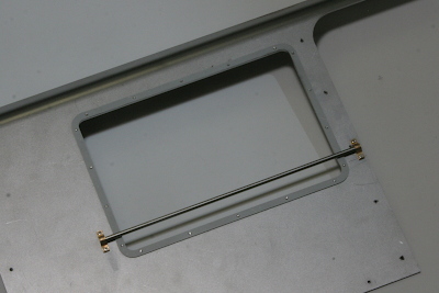
The sunshade above the side windows required bending, but the parts were laser-cut in their flat, developed form. I used 0.8 mm steel sheet for this component.
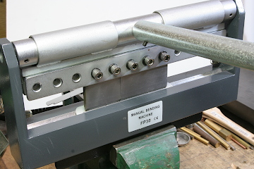
The shape requires separate bends for the central mounting section and the curved sections on both sides. I bent the central section first, removing some of the brake fingers so they would not interfere with the curved areas. The side curves were formed using a flat steel bar whose end had been ground to the required radius and used as a forming die.
Shown here mounted on the window, the central mounting section overlaps the top of the window frame and is secured using the same screws that hold the window frame itself.
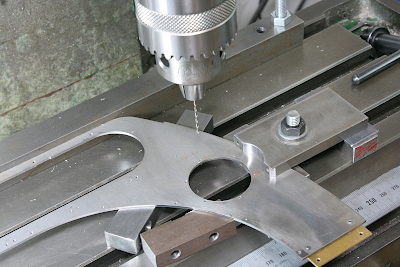
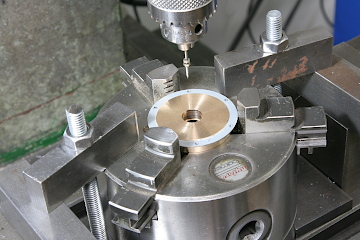
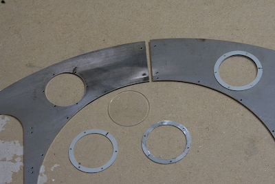
Next, I turned to the front cab panel. There are two round windows near the front panel center, consisting of a circular glass disks clamped between front and rear window frames. The first step was drilling the mounting holes in the front panel for these frames, using an XY table to maintain precise positioning.
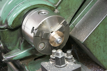
The laser-cut window frames are thin and prone to distortion. To prevent this, I made a brass holding fixture and clamped the frames in it with a three-jaw chuck during drilling. The front frame received plain through-holes, while the rear frame was tapped.
For the glass, I found a perfectly sized crystal intended for wristwatches. With the front panel thickness at 1.6 mm and the glass thickness at 1.5 mm, the glass fits neatly into the opening and is secured by clamping it from both sides. On the full-size prototype, the frames are riveted, but here the heads of miniature screws are used to represent the rivets.