< Brake System 3 >
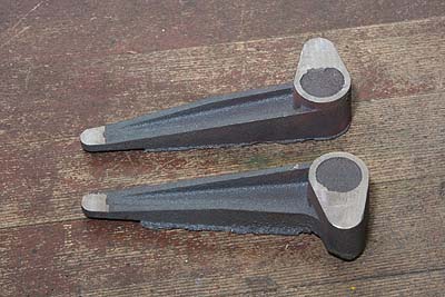
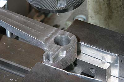
The brake rods are pulled by a brake cylinder
through cast iron brake arms. The photo shows
the cast arms after cutting outside faces.
The arms convert the movement from vertical
to horizontal and increase the force. So
the casting is comparatively big and solid.
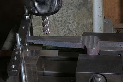
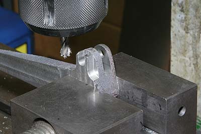
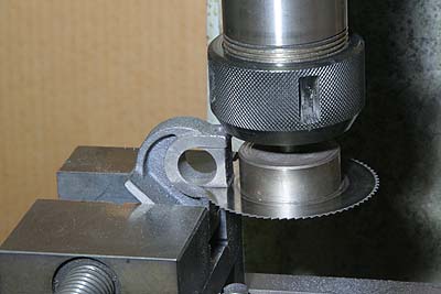
Backside profile of the casting consists
of two parallel faces at both ends and one
slant between the ends. The photo shows cutting
the slant.
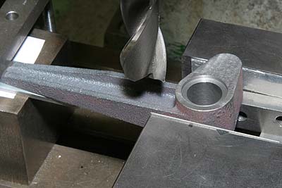
The large axle hole is opened by drill and
end mill.
Connecting holes at both ends are also opened.
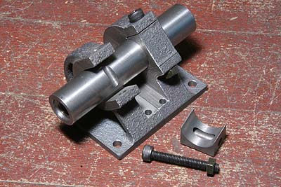
Parallel ribs and a slit are cut by end mill.
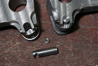
Connecting pin at the shorter arm is secured
by a screw and a nut. Note the screw is offset
from center of the pin.
Two brake arms are bound in a brake shaft.
And the shaft is fixed in cast iron brackets.
The shaft also secured by crossing screws.
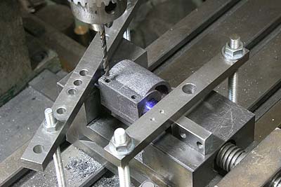
Hole for the screw is opened in both the
bracket and the shaft at a time.
The bracket hole is parted in two halves
by 0.3mm slitting saw. It is because the
shaft has to be mounted from underneath.
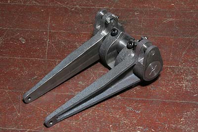
The shaft is locked in the brackets and the
both arms rotate independently around the
shaft.
The arms are secured at both ends of the
shaft with screw flange sets, same as the
driving wheels' crank pins.
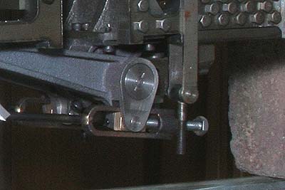
The brackets are mounted under one of the
chassis stretchers. Rear ends of the brake
rods are connected to the arms with gunmetal
die blocks. The die blocks are push from
back by adjusting bolts. After adjustment,
the bolts are secured with lock nuts.
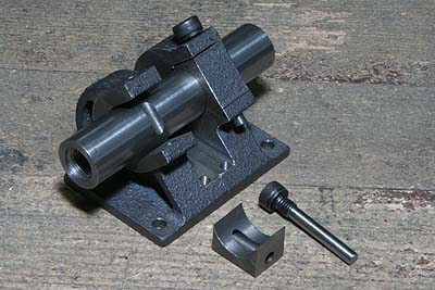
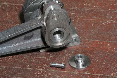
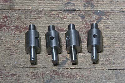
I modified the brake shaft securing screws
and holes so as to do away with the nuts.
The new screw was cut from a larger size
screw. (Compare with the forth photo before
it)
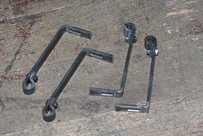
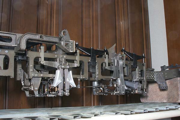
Vertical linkage of the brake system caused
drooping of the parts. So the prototype employs
many kinds of hooks. The photo shows L-shape
hooks to keep the first and second brake
beams horizontal.
The hook is made from rectangle section steel
bar, annealed and bent as the photo.
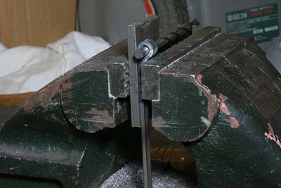
The photo shows studs to hold the L-shape
hooks. They are screwed into the main frames
from inside. And the hooks are held at opposite
ends with cotter pins.
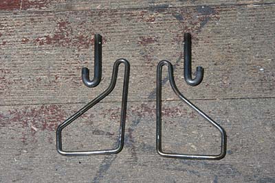
The third brake beam is hung by triangle
rings. The rings are made from stainless
steel wire, bent and silver-soldered at the
bottom. The J-shape hooks hang the triangle
rings. The hooks go through the main frame
and secured with cotter pins.
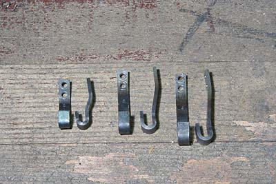
These are hooks for the brake rods. They
are also made from rectangle section steel
bar.
The whole brake system is assembled tentatively
without driving wheels. Every connecting
pins and holes has suitable play, in order
to allow the second brake shoes move just
2mm left and right from the center.
The remaining job of the brake system is
the steam brake cylinder.